CALREC
Putting Sound in the Picture
45
Testing/certification
Calrec strongly recommend that all
Hydra2 network cabling is properly
tested or certified prior to on-site
commissioning of the system. Simple
test devices that only check the pin-out
of the terminations are not sufficient to
prove the performance and reliability of
high speed data cabling. Certification
level test equipment can give a simple
pass / fail response but in doing so will
test various important factors as well as
pin-out. Certification type tests include
determining cable length, measuring skew
(timing differences between pairings
due to variations in length caused by
intentional differences in twist rate),
measuring for loss, signal to noise ratio
and BERT error checking on data.
Cables that fail certification tests or fail
to perform, may appear to function fine
and therefore the full length of the cable
conforms to its’ intended specification.
Slide on outer boots offer additional
strain-relief protection but are not
sufficient on their own. In order to be able
to crimp the cable jacket inside the RJ45
and land the data cores on the terminals,
the amount that the jacket is stripped
back in relation to the cores needs to be
quite accurate. Cables with exposed data
cores should not be used as they will be
unreliable.
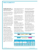
Termination-pin-out
Hydra2 network cables use the standard
gigabit Ethernet pin-out. Performance
relies on the positive and negative leg
of each signal pair using cores that are
twisted together. Calrec recommends that
'straight-through' or 'pin-for-pin' cables
are used. 'Cross-over' style cables can
be used, however they must be gigabit
standard cross-over. Older pin-outs,
designed for use with slower Ethernet
standards only use two of the four pairs,
even though all four pairs are terminated.
Cross-over variants of this style only cross
the pairs that are used (A & B). Gigabit
cross-over cables require that the blue (C)
pair is crossed with the brown (D) pair as
well as the orange (A) pair being crossed
with the blue (B) pair.
STANDARD HYDRA2 RJ45 PIN-OUT
Pin
Colour
Signal
1
Orange-White
A+
2
Orange
A -
3
Green-White
B+
4
Blue
C+
5
Blue-White
C -
6
Green
B -
7
Brown-White
D+
8
Brown
D -
1
8
Top
Front
1
8
RJ45 PIN NUMBERING
• For standard wiring, both
ends of the cable should be
terminated as above
in other applications, such as a PC LAN
connection where errors leading to retries
and therefore delays are acceptable and
often unnoticed.
Temporary/reusablecables
Cabling that is not part of a permanent
infrastructure, such as temporary runs
used for outside broadcasts should be
carefully coiled and uncoiled to avoid
kinking and they should be regularly
tested. Cables showing any sign of
damage should be replaced.
Summary of Contents for Artemis
Page 5: ...calrec com Putting Sound in the Picture ARTEMIS INFORMATION...
Page 9: ...calrec com Putting Sound in the Picture ARTEMIS CONTROL SURFACE...
Page 26: ...26 ARTEMIS Digital Broadcast Production Console...
Page 27: ...calrec com Putting Sound in the Picture ARTEMIS PROCESSING CORE BEAM SHINE...
Page 33: ...calrec com Putting Sound in the Picture ARTEMIS PROCESSING CORE LIGHT...
Page 40: ...40 ARTEMIS Digital Broadcast Production Console...
Page 41: ...calrec com Putting Sound in the Picture ARTEMIS CONNECTION INFORMATION...
Page 66: ...66 ARTEMIS Digital Broadcast Production Console...
Page 67: ...calrec com Putting Sound in the Picture ARTEMIS EXTERNAL CONTROL...
Page 80: ...80 ARTEMIS Digital Broadcast Production Console...
Page 81: ...calrec com Putting Sound in the Picture ARTEMIS SETUP CONFIGURATION...
Page 100: ...100 ARTEMIS Digital Broadcast Production Console...
Page 101: ...calrec com Putting Sound in the Picture ARTEMIS PANEL OPTIONS...
Page 110: ...110 ARTEMIS Digital Broadcast Production Console...
Page 111: ...calrec com Putting Sound in the Picture ARTEMIS OBSOLETE PANELS...
Page 114: ...114 ARTEMIS Digital Broadcast Production Console...
Page 115: ...calrec com Putting Sound in the Picture ARTEMIS SPECIFICATIONS...

