30 ARTEMIS
Digital Broadcast Production Console
Processing Core – Beam / Shine
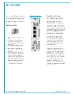
4 x BNC connectors provide sync inputs,
allowing for redundancy and a range of
formats. Two inputs are for SD / HD
video sync signals, one for AES DARS and
one for TTL Wordclock.
The upper section of the core also
contains LED indication to show the
status of the fans fitted within. Failures
are also reported by the console's System
Status.
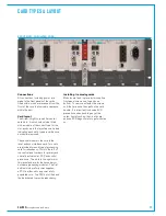
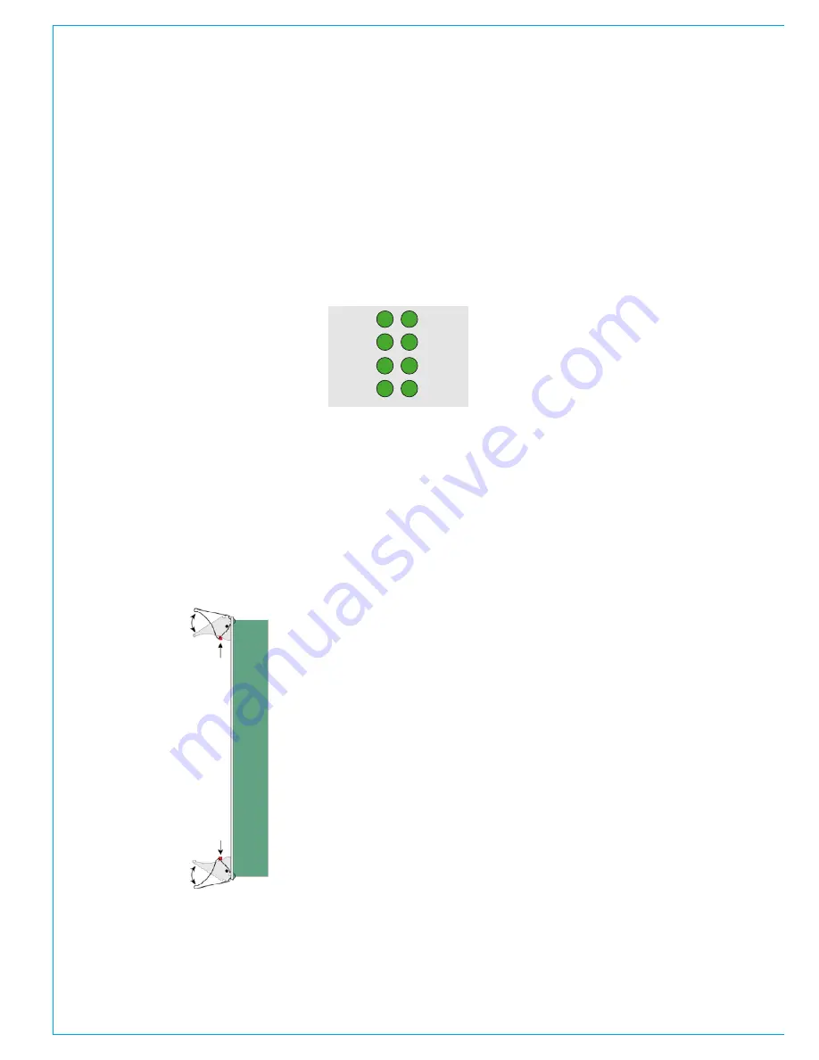
Installing/removingcards
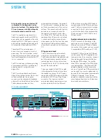
To remove a module from the core, take
hold of both top and bottom card handles,
press both of the red latches and open the
card handles outwards to lever the module
away from the backplane connectors.
The module can then be slid out of the
core. Avoid touching any exposed parts
of the circuit board unless observing ESD
precautions.
To install a module, line up the card edges
with the card guides in the core slot and
gently slide it in. Ensure the handles are
in the open position and push the card
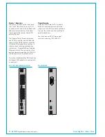
POK
MA
RST
NOK
ST2
PRI
MOK
ST1
fully into the core whilst closing the card
handles to lever the module into place.
A click should be heard when the module
is seated fully.
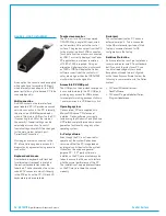
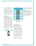
StandardStatusLED's
Control, DSP and router cards have a
standard set of front panel status LED's.
Depress red latches
Open card handles
outwards to lever
the module out.
Close card handles
inwards to lever the
module into place
• POK - Power OK, module is receiving
power.
• MA - Module active. Indicates which of
the primary / secondary pair is actively
in control.
• PRI - Indicates if the module is fitted in
a primary slot.
• RST - Illuminates when the module
receives a reset command.
• MOK - Module OK. Indicates the
module has booted and is running,
either actively or as a hot-spare.
• NOK - Neighbour OK. Indicates the
presence and status of the alternate
card of the same type. Neighbours
are primary / secondary counterparts,
rather than physically adjacent
modules.
• ST1 & ST2 are Calrec engineering
status LED's, the function of which
varies by card type and can be subject
to change with software version.
Summary of Contents for Artemis
Page 5: ...calrec com Putting Sound in the Picture ARTEMIS INFORMATION...
Page 9: ...calrec com Putting Sound in the Picture ARTEMIS CONTROL SURFACE...
Page 26: ...26 ARTEMIS Digital Broadcast Production Console...
Page 27: ...calrec com Putting Sound in the Picture ARTEMIS PROCESSING CORE BEAM SHINE...
Page 33: ...calrec com Putting Sound in the Picture ARTEMIS PROCESSING CORE LIGHT...
Page 40: ...40 ARTEMIS Digital Broadcast Production Console...
Page 41: ...calrec com Putting Sound in the Picture ARTEMIS CONNECTION INFORMATION...
Page 66: ...66 ARTEMIS Digital Broadcast Production Console...
Page 67: ...calrec com Putting Sound in the Picture ARTEMIS EXTERNAL CONTROL...
Page 80: ...80 ARTEMIS Digital Broadcast Production Console...
Page 81: ...calrec com Putting Sound in the Picture ARTEMIS SETUP CONFIGURATION...
Page 100: ...100 ARTEMIS Digital Broadcast Production Console...
Page 101: ...calrec com Putting Sound in the Picture ARTEMIS PANEL OPTIONS...
Page 110: ...110 ARTEMIS Digital Broadcast Production Console...
Page 111: ...calrec com Putting Sound in the Picture ARTEMIS OBSOLETE PANELS...
Page 114: ...114 ARTEMIS Digital Broadcast Production Console...
Page 115: ...calrec com Putting Sound in the Picture ARTEMIS SPECIFICATIONS...

