42 ARTEMIS
Digital Broadcast Production Console
Connection Information
SFP
- OVERVIEW
The connections between control
surface and processing core, as well
as all Hydra2 network connections,
connections between I/O boxes
and routers, and router-to-router
connections between different cores,
are made via SFP modules (Small
Form-factor Pluggable).
SFPs can be provided for RJ45 copper
connections, as well as for singlemode or
multimode fibre on LC connectors. This
allows for each port’s connection type
to be chosen depending on the distance
of the run or to match the infrastructure
present. SFPs can easily be changed on
a port by port basis as and when required.
The correct quantity of SFPs are supplied
pre-fitted. The type of each connection
- copper, singlemode fibre or multimode
fibre, should be specified at the time of
order to ensure the correct SFP types
are supplied. Additional SFP modules
can be ordered if required. If a system is
to be connected to an existing Hydra2
network, please discuss this with your
Calrec project leader, sales person or
local distributor to ensure that SFPs are
provided and ports provisioned for the
additional router to router connections.
SFP MODULES
1
3
5
7
2
4
6
8
16
15
SFP
PORTS
2
INTERFACE
6
7 5 4 3 2 1 0
ADDRESS 1
1
0
0
1
R
Y
H D
A
1
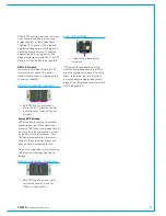
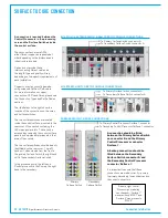
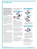
ROUTER CARD SFP ORIENTATION
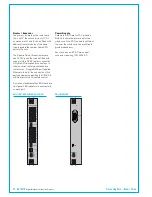
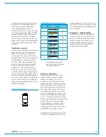
FIXED FORMAT I/O BOX SFPS
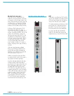
• Router card shown with copper
SFPs fitted in ports 1-4,
singlemode fibre (button release)
in ports 5-8.
• I/O box shown with singlemode
fibre SFPs (button release) fitted.
• Both SFP types above
have a handle latching
mechanism, shown in the
locked position. The unit
on the left is a singlemode
duplex LC fibre module.
The unit on the right is a copper
RJ45 module.
STATUS
H2 I/F
RESET
WCLK OUT
1
2
HB1
SOFT
CTRL2
AUD2
PSU2
H_ACT
HB2
CTRL1
AUD1
PSU1
FAN1
FAN2
FAN 12V
MODULAR I/O BOX SFPS
• Modular I/O controller card SFPs
are both orientated the same way
around (Button release singlemode
fibre SFPs shown).
SFPslotorientation
SFP modules plug into front panel slots
on router and modular I/O controller
cards, and rear panel slots on fixed format
I/O boxes. The modules can be fitted or
removed whilst the system is powered and
without removing or opening any card or
box cases.
Note the orientation of the SFP modules,
as shown in the illustrations on this
page - modules fitted in even numbered
router ports (left hand column) are fitted
the opposite way around to those in the
odd numbered router ports (right hand
column). Likewise for fixed format I/O
boxes, the primary SFP module is the
opposite way around to the secondary
SFP module. The modules are orientated
so that the release catch for the RJ45 /
LC connector plugs once inserted are on
the outside edge.
For modular I/O box controller cards,
both SFP slots are orientated so that
the release catch on the cable / fibre
connector are on the right-hand side.
SFPlatchingandextraction
Calrec source SFP modules from various
manufacturers. All types used conform
to the same specification, however the
latching mechanism on them can vary
slightly.
The standard copper SFP, and some fibre
SFPs as shown in the photograph on the
previous page have latch / extraction
handles. On insertion, the handles should
be set against the outer edge (the same
side as the release catch on the RJ45 /
LC connector plug that fits into the SFP)
to lock it into place and prevent accidental
removal if cables are pulled.
To remove this style of SFP, remove the
cable / fibre and slide the handle (copper)
or lift the handle out (fibre) to the inside
edge position as shown in the diagram
below. The module can then be removed
by pulling on the handle.
Summary of Contents for Artemis
Page 5: ...calrec com Putting Sound in the Picture ARTEMIS INFORMATION...
Page 9: ...calrec com Putting Sound in the Picture ARTEMIS CONTROL SURFACE...
Page 26: ...26 ARTEMIS Digital Broadcast Production Console...
Page 27: ...calrec com Putting Sound in the Picture ARTEMIS PROCESSING CORE BEAM SHINE...
Page 33: ...calrec com Putting Sound in the Picture ARTEMIS PROCESSING CORE LIGHT...
Page 40: ...40 ARTEMIS Digital Broadcast Production Console...
Page 41: ...calrec com Putting Sound in the Picture ARTEMIS CONNECTION INFORMATION...
Page 66: ...66 ARTEMIS Digital Broadcast Production Console...
Page 67: ...calrec com Putting Sound in the Picture ARTEMIS EXTERNAL CONTROL...
Page 80: ...80 ARTEMIS Digital Broadcast Production Console...
Page 81: ...calrec com Putting Sound in the Picture ARTEMIS SETUP CONFIGURATION...
Page 100: ...100 ARTEMIS Digital Broadcast Production Console...
Page 101: ...calrec com Putting Sound in the Picture ARTEMIS PANEL OPTIONS...
Page 110: ...110 ARTEMIS Digital Broadcast Production Console...
Page 111: ...calrec com Putting Sound in the Picture ARTEMIS OBSOLETE PANELS...
Page 114: ...114 ARTEMIS Digital Broadcast Production Console...
Page 115: ...calrec com Putting Sound in the Picture ARTEMIS SPECIFICATIONS...

