60 ARTEMIS
Digital Broadcast Production Console
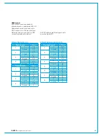
Connection Information
Router /
Processing
Core
Audio I/O
Audio I/O
Audio I/O
Audio I/O
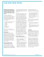
Router /
Processing
Core
Audio I/O
Audio I/O
Audio I/O
Audio I/O
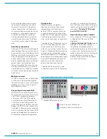
Router /
Processing
Core
Audio I/O
Audio I/O
Audio I/O
Audio I/O
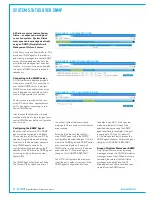
Router /
Processing
Core
Audio I/O
Audio I/O
Audio I/O
Audio I/O
Router /
Processing
Core
Audio I/O
Audio I/O
Audio I/O
Audio I/O
Router /
Processing
Core
Audio I/O
Audio I/O
Audio I/O
Audio I/O
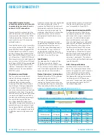
CONNECTING TO OTHER CONSOLES/ROUTERS
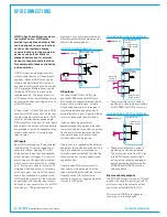
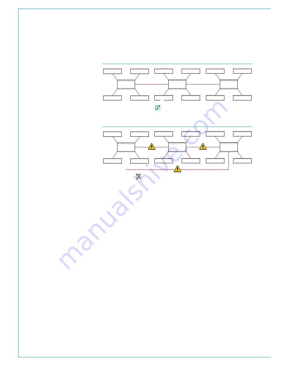
FIGURE 1 - CORRECT CONNECTION OF A THREE CONSOLE NETWORK
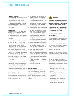
FIGURE 2 - INCORRECT CONNECTION OF A THREE CONSOLE NETWORK
Three router cores connected with no duplicate paths.
Incorrect connection! The additional link creates a duplicate path.
Multiple Apollo and Artemis consoles
can be connected together and to
standalone Hydra2 routers, allowing
them to share each other's I/O
resources. Before connecting a
console to an active Hydra2 network it
is essential to be aware of IP address
compatibility and of the Master Router
status.
A single, standalone console with its
processing core and connected I/O units
forms a basic Hydra2 network. All Hydra2
networks require one, and only one of
the processing cores to be configured as
the Master Router. Therefore, consoles
specified at order to be standalone
will have their processing cores pre-
configured as Master Routers. It is vital
that this is changed before connecting
to an active Hydra2 network. A console
specified to be part of a wider Hydra2
network will not function reliably until it
is connected to a network with a Master
Router, or has its own core changed to
become a Master. Please contact Calrec
support for guidance on configuring router
master / slave status.
Each processing core is configured with
an IP address range unique within the
network it is to be connected to. It is
important to ensure that the IP address
range does not conflict before connecting
to an existing network.
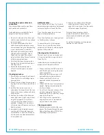
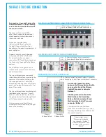
Processing cores connect together using
any of their primary main router I/O ports,
highlighted on the following page. These
core-to-core connections should NOT be
made via expansion slot ports.
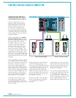
To provide redundancy, for each primary
router to router link, there should also be a
(normally inactive) link fitted between the
secondary router cards in the same cores.
When multiple cores are networked, it
is essential that they are all receiving
and are locked to the same derived
sync reference.
Each Hydra2 link can carry 512 channels
of audio in each direction simultaneously.
From software version 1.10, bandwidth
between cores can be increased in
multiples of 512 audio channels by adding
additional links to form trunks.
Trunk links should only be fitted if
they have been configured.
Please
contact Calrec Customer Support or your
local representative for guidance on trunk
link configuration.
It is important that there is only one path
(not counting dedicated secondaries
and configured trunks) between any two
points on the network. It is important to
note that the path between I/O port and
console router may pass through other
routers. Figure 2 shows an incorrectly
connected network - the addition of a
third router to router link creates duplicate
paths. This will cause network collisions
as data can take two paths between any
two routers - one path is direct, the other
is via the third router. Removing any one
of the three router to router links corrects
this, effectively changing the topology to
match that shown in Figure 1.
Note, it is important to ensure that
when Hydra2 routers are networked
together, they are on separate VLANs.
Summary of Contents for Artemis
Page 5: ...calrec com Putting Sound in the Picture ARTEMIS INFORMATION...
Page 9: ...calrec com Putting Sound in the Picture ARTEMIS CONTROL SURFACE...
Page 26: ...26 ARTEMIS Digital Broadcast Production Console...
Page 27: ...calrec com Putting Sound in the Picture ARTEMIS PROCESSING CORE BEAM SHINE...
Page 33: ...calrec com Putting Sound in the Picture ARTEMIS PROCESSING CORE LIGHT...
Page 40: ...40 ARTEMIS Digital Broadcast Production Console...
Page 41: ...calrec com Putting Sound in the Picture ARTEMIS CONNECTION INFORMATION...
Page 66: ...66 ARTEMIS Digital Broadcast Production Console...
Page 67: ...calrec com Putting Sound in the Picture ARTEMIS EXTERNAL CONTROL...
Page 80: ...80 ARTEMIS Digital Broadcast Production Console...
Page 81: ...calrec com Putting Sound in the Picture ARTEMIS SETUP CONFIGURATION...
Page 100: ...100 ARTEMIS Digital Broadcast Production Console...
Page 101: ...calrec com Putting Sound in the Picture ARTEMIS PANEL OPTIONS...
Page 110: ...110 ARTEMIS Digital Broadcast Production Console...
Page 111: ...calrec com Putting Sound in the Picture ARTEMIS OBSOLETE PANELS...
Page 114: ...114 ARTEMIS Digital Broadcast Production Console...
Page 115: ...calrec com Putting Sound in the Picture ARTEMIS SPECIFICATIONS...

