75
A second special case can arise if the outside lines are con
fi
gured to allow a switch-hook (
fl
ash)
to be sent to the outside line. A switch-hook to an outside line may be needed to affect certain
features like Call Waiting. However, some Central Of
fi
ce switches may give a new dial tone in
response to the switch-hook. In this case, the caller could possibly dial an allowed number, send
the switch-hook, and then dial a restricted number. The IPS is only able to examine the digits
dialed starting at the beginning of the sequence and the call would not be from being sent to an
outside line. (see “Programming Outside Lines”, page 48)
Filling The Call Barring Allow And Disallow Tables
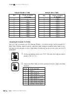
The system can store up to three call barring Allow Tables and three Disallow Tables. Each table
has 10 slots (numbered 0 to 9). Each slot stores one phone number or pre
fi
x. (See the sample table
on following page)
You must program all 10 slots for the table to work. If a slot is to be left empty, you must still
program it as an “empty” slot by simply hanging up, as described below. You can clear all slots of
all tables by entering the “Clear Speed Dialing And Call Barring Tables” command on page 81.
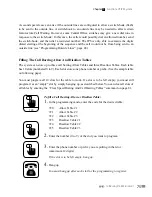
To fi ll a Call Barring Allow or Disallow Table:
1.
In the programming mode, enter the code for the desired table:
720
Allow
Table
#1
721
Allow
Table
#2
722
Allow
Table
#3
723
Disallow
Table
#1
724
Disallow
Table
#2
725
Disallow
Table
#3
2.
Enter the number (0 to 9) of the slot you want to program.
3.
Enter the phone number or pre
fi
x you are putting in that slot .
(maximum 12 digits)
If the slot is to be left empty, hang up.
4.
Hang up
You must hang up after each slot for the programming to register.
720
Call Baring (Toll Restriction)
Chapter
3
- Functions Of IPS System


