


4.4 PCIe Link Sequence
4-17
4
O
per
ation
4.4.3 PCIe Link Sequence Start
Press the PCIe Compliance Base Board reset switch before starting
measurement. Then click Sequence Start to start the link training
sequence.
The button name changes to Stop while the link training sequence is
being sent. The button name changes to Unlink once the link training
sequence is successfully sent and the PPG status changes from Electrical
Idle to Loopback Active. A test pattern is sent from the PPG here.
Clicking Unlink while the test pattern is being sent aborts the test
pattern transmission, and the PPG returns to Electrical Idle status.
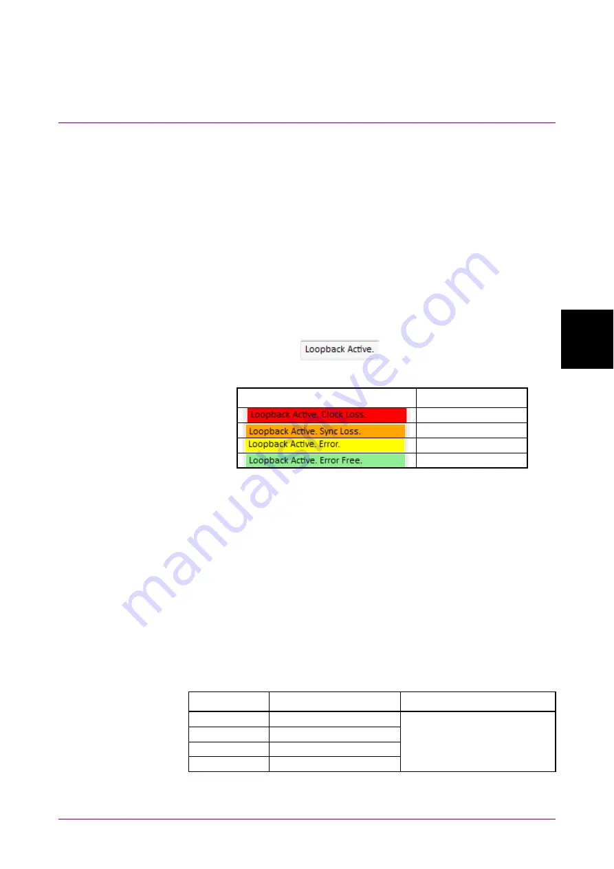
Successful linking can be confirmed using the device debugging function
or MX183000A screen. The Loopback Active display will change as
follows depending on the 32G ED status. When MX183000A is not
connected 32G ED,
is displayed.
Table 4.4.3-1 Link Status Confirmation
Loopback Active. display
32G ED status
Clock Loss
Sync Loss
Error
Error Free
If you wish to measure Jitter Tolerance after this, refer to 4.6 “Jitter
Tolerance Test” for details of the Run Test tab, Graph tab, and Report
tab.
If you wish to measure BER after this, click BER Measurement.
Selecting BER Monitor displays the BER measurement results. The
pass/fail judgment criteria are determined by the value selected in
Specification. (See Table 4.4.3-2.)
This function is enabled when the link training sequence is successfully
sent and the PPG status is Loopback Active. This is displayed only when
32G ED is installed.
Table 4.4.3-2 BER Measurement Pass/Fail Judgment
Specification
Measurement time [s]
Pass/fail judgment condition
1.0/1.1
400
Pass if the error count does
not exceed 1 after the
measurement time on the left.
2.0
200
3.0/3.1
125
4.0
63
Summary of Contents for MX183000A
Page 12: ...xii ...
Page 16: ...IV ...
Page 20: ...Chapter 1 Outline 1 4 Figure 1 1 3 Jitter Tolerance Graph Screen ...
Page 54: ...Chapter 3 Connecting Equipment 3 16 ...
Page 136: ...Chapter 5 Remote Control 5 30 Figure 5 8 2 Sequence Screen BER Measurement 10 8 9 11 ...
Page 206: ...Chapter 5 Remote Control 5 100 ...
Page 218: ...Appendix A Specifications A 12 ...
Page 226: ...Appendix B Default Settings B 8 ...