


The reach of phase overcurrent line protection is dependent of the operation state and the
fault type. Therefore the setting must be based on fault calculations made for different
faults, fault points and switching states in the network. Although it is possible to make
hand calculations of the different faults it is recommended to use computer based fault
calculations. Different time delay principles can be used. This is due to different praxis.
The following principle for the phase overcurrent protection is proposed:
•
Step 1 (I>>>) with high current setting and zero delay. This step gives fast trip for the
line short circuits close to the nearest line end.
•
Step 2 (I>>) with a current setting that enables detection of all short circuits on the
protected line and on the local and remote busbars. The function has a short delay to
enable selectivity.
•
Step 3 (I>) with a current setting that enables detection of all short circuits on the
adjacent lines connected to the local and remote busbars. The function has a longer
delay to enable selectivity.
2
1
4
5
6
A
B
7
8
9
10
80 %
Y
Y
REL 650
3
ANSI11000114_1_en.vsd
REL 650
ANSI11000114 V1 EN
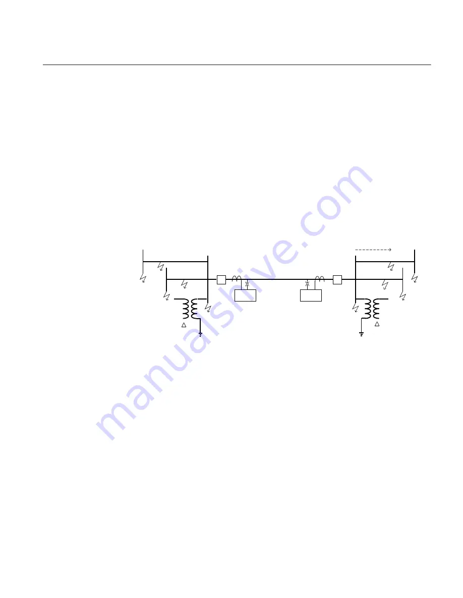
Figure 21:
Fault points for phase overcurrent setting calculations
The phase overcurrent protection in line end A is considered in this example. The same
principle can be used for line end B.
3.1.9.1
Calculating general settings
1.
Set
GlobalBaseSel
to
1
The settings are made in primary values. These values are given in the base settings
in Global base 1.
2.
Set
DirModeSel1(2,3)
to
Non-directional
It is assumed that the phase overcurrent protection shall operate also when the
distance protection is deactivated due to fuse failure. Therefore the function shall be
non-directional as the directional function must use voltage measurement.
1MRK 506 334-UUS A
Section 3
REL650 setting examples
67
Application manual
Summary of Contents for REL650 series
Page 1: ...Relion 650 series Line distance protection REL650 ANSI Application manual...
Page 2: ......
Page 30: ...24...
Page 99: ...IED IED ANSI05000460 V2 EN 1MRK 506 334 UUS A Section 4 Analog inputs 93 Application manual...
Page 110: ...104...
Page 260: ...254...
Page 274: ...268...
Page 280: ...274...
Page 396: ...390...
Page 494: ...488...
Page 506: ...500...
Page 515: ...509...


