


4.7 Auto-Tuning
YASKAWA ELECTRIC
SIEP C710636 02B YASKAWA U1000 Technical Manual
159
St
ar
t-
Up Pr
ogr
ammi
ng
&
O
p
er
at
io
n
4
■
Notes on Inertia Tuning and ASR Gain Auto-Tuning
WARNING!
Electrical Shock Hazard. When executing Inertia Tuning or ASR Gain Auto-Tuning, voltage is applied to the motor even
before it rotates. Do not touch the motor until Auto-Tuning is completed. Failure to comply may result in injury from electrical shock.
• Both tuning methods must be performed with the machine connected to the motor but without load applied.
• The motor will rotate during the Auto-Tuning process. Make sure the areas around the motor and connected machinery
are clear.
• The drive will let the system rotate at a certain speed while superimposing a sine wave test signal. Make sure this
tuning process does not cause any problem or malfunction in the machine before using it.
• Ensure the motor-mounted brake is fully released if installed.
• Connected machinery should be allowed to rotate the motor.
◆
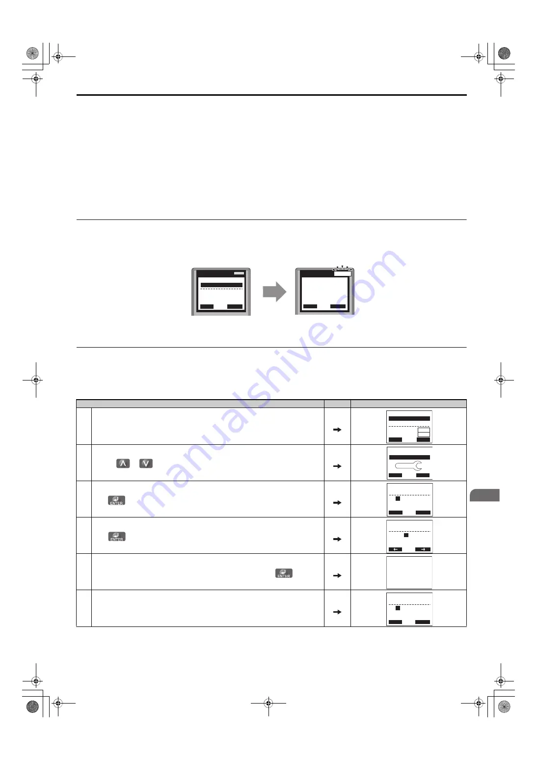
Auto-Tuning Interruption and Fault Codes
If tuning results are abnormal or the STOP key is pressed before completion, Auto-Tuning will be interrupted and a fault
code will appear on the digital operator.
Figure 4.16
Figure 4.17 Auto-Tuning Aborted Display
◆
Auto-Tuning Operation Example
The following example demonstrates Rotational Auto-Tuning when using OLV (A1-02 = 2) and CLV (A1-02 = 3).
■
Selecting the Type of Auto-Tuning
A – During Auto-Tuning
B – Auto-Tuning Aborted
Step
<1> T1-00 will appear on the display when one of the multi-function inputs has been set to switch between motor 1 and motor 2 (H1-
= 16).
Display/Result
1.
Turn on the power to the drive. The initial display appears.
2.
Press the
or
key until the Auto-Tuning display appears.
3.
Press
. T1-01 and the current setting 0 (Rotational Auto-Tuning) are displayed.
4.
Press
. The setting of T1-01 flashes and can be changed.
5.
The setting is already 0 (Rotational Auto-Tuning). Do not change the setting and press
.
6.
The display automatically returns to the display shown in Step 3.
DIGITAL OPERATOR JVOP-180
DIGITAL OPERATOR JVOP-180
REV
DRV
FOUT
DRV
ALM
ALM
- A.TUNE -
X.XX Hz/ X.XXA
DRV
Tune Proceeding
Rdy
FWD
- MODE -
Er-03
STOP key
DRV
FWD
RESET
- MODE -
U1-01= 0.00Hz
U1-02= 0.00Hz
U1-03= 0.00A
DRV
FREF (AI)
Rdy
RSEQ
RREF
FWD
JOG
HELP
- MODE -
PRG
Auto-Tuning
DATA
AUTO
FWD
- A.TUNE -
T1-
01
= 0
∗
0
∗
Standard Tuning
PRG
Tuning Mode Sel
ESC
FWD
DATA
- A.TUNE -
T1-01=
0
∗
0
∗
Standard Tuning
PRG
Tuning Mode Sel
FWD
“0”
Entry Accepted
- A.TUNE -
T1-
01
= 0
∗
0
∗
Standard Tuning
PRG
Tuning Mode Sel
ESC
FWD
DATA
SIEP_C710636_02B_1_0.book 159 ページ 2015年11月25日 水曜日 午後4時56分


