CYLINDER AND PISTON
5-33
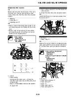
b. If out of specification, rebore or replace the
cylinder, and replace the piston and the pis-
ton rings as a set.
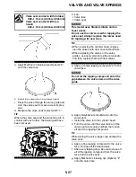
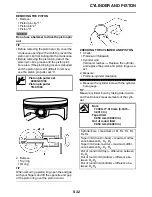
c. Measure the piston outside diameter “a” at
the measuring point (from piston skirt bot-
tom) “b” with the micrometer.
d. If out of specification, replace the cylinder,
the piston, and the piston rings as a set.
e. Calculate the piston-to-cylinder clearance
with the following formula.
f. If out of specification, replace the cylinder,
the piston, and the piston rings as a set.
▲▲▲▲▲▲▲▲▲▲▲▲▲▲▲▲▲▲▲▲▲▲▲▲▲▲▲▲▲▲▲▲
EASB296233
CHECKING THE PISTON RINGS
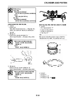
1. Measure:
• Piston ring side clearance
Out of specification
Replace the piston
and piston rings as a set.
TIP
Before measuring the piston ring side clear-
ance, eliminate any carbon deposits from the
piston ring grooves and piston rings.
2. Install:
• Piston rings
TIP
Level the piston ring into the cylinder with the
piston.
3. Measure:
• Piston ring end gap
Out of specification
Replace the piston
ring.
TIP
The oil ring expander’s end gap cannot be
measured. If the oil ring rail’s gap is excessive,
replace all three oil rings.
Diameter
76.955–76.970 mm (3.0297–
3.0303 in)
Measuring point (from piston
skirt bottom)
6.0 mm (0.24 in)
Piston-to-cylinder clearance =
Cylinder bore - Piston diameter
Piston-to-cylinder clearance
0.030–0.055 mm (0.0012–0.0022
in)
Limit
0.15 mm (0.006 in)
b
a
Ring side clearance
0.030–0.065 mm (0.0012–0.0026
in)
Limit
0.115 mm (0.0045 in)
a. 10 mm (0.39 in)
Содержание YZ 2016 Series
Страница 6: ...EASB296006 YAMAHA MOTOR CORPORATION U S A YZ MOTORCYCLE LIMITED WARRANTY...
Страница 10: ......
Страница 31: ...CONTROL FUNCTIONS 1 19 a 2...
Страница 63: ...LUBRICATION POINTS AND LUBRICANT TYPES 2 22...
Страница 66: ...LUBRICATION SYSTEM CHART AND DIAGRAMS 2 25...
Страница 68: ...LUBRICATION SYSTEM CHART AND DIAGRAMS 2 27...
Страница 69: ...LUBRICATION SYSTEM CHART AND DIAGRAMS 2 28 1 Exhaust camshaft 2 Intake camshaft 3 Oil filter element 4 Oil pump...
Страница 70: ...LUBRICATION SYSTEM CHART AND DIAGRAMS 2 29...
Страница 71: ...LUBRICATION SYSTEM CHART AND DIAGRAMS 2 30 1 Camshaft 2 Oil pressure check bolt 3 Oil filter element 4 Oil pump...
Страница 72: ...CABLE ROUTING DIAGRAM 2 31 EASB296066 CABLE ROUTING DIAGRAM...
Страница 74: ...CABLE ROUTING DIAGRAM 2 33...
Страница 76: ...CABLE ROUTING DIAGRAM 2 35...
Страница 78: ...CABLE ROUTING DIAGRAM 2 37...
Страница 80: ...CABLE ROUTING DIAGRAM 2 39...
Страница 82: ...CABLE ROUTING DIAGRAM 2 41...
Страница 84: ...CABLE ROUTING DIAGRAM 2 43...
Страница 86: ...CABLE ROUTING DIAGRAM 2 45...
Страница 239: ...ELECTRIC STARTER 5 40 5 Install Bolt 1 O ring 2 TIP Apply the lithium soap based grease on the O ring New...
Страница 262: ...OIL PUMP AND BALANCER GEAR 5 63 a 2 10 b 2 9 1 b 5 3 a 4 10 5 9 3 E c d 6 7 8 8 b 6...
Страница 282: ...TRANSMISSION 5 83...
Страница 302: ...8 CHECKING THE INTAKE AIR TEMPERATURE SENSOR 8 68 CHECKING THE FUEL INJECTOR 8 68...
Страница 317: ...CHARGING SYSTEM 8 15...
Страница 321: ...COOLING SYSTEM For JPN 8 19...
Страница 351: ...FUEL PUMP SYSTEM 8 49...
Страница 352: ...ELECTRICAL COMPONENTS 8 50 EASB296346 ELECTRICAL COMPONENTS EASB296347 7 8 9 1 3 2 4 5 6...
Страница 354: ...ELECTRICAL COMPONENTS 8 52 11 10 9 2 3 1 6 7 8 4 5...
Страница 356: ...ELECTRICAL COMPONENTS 8 54 EASB296348 CHECKING THE SWITCHES 4 1 3 2 B B Sb B B B B B B B B...
Страница 357: ...ELECTRICAL COMPONENTS 8 55 1 Engine stop switch 2 Neutral switch 3 Clutch switch 4 Start switch...
Страница 378: ...LIST OF SELF DIAGNOSTIC AND FAIL SAFE ACTIONS 9 7...
Страница 392: ...ON OFF ON OFF Gy Gy B B Gy B B B L L B B B B B YZ250FXG 2016 WIRING DIAGRAM B29 28199 11_W D indd 2 2015 06 15 13 19 32...


