ELECTRICAL COMPONENTS
8-64
▼▼▼▼▼▼▼▼▼▼▼▼▼▼▼▼▼▼▼▼▼▼▼▼▼▼▼▼▼▼▼▼
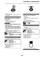
a. Connect the lean angle sensor coupler to
the wire harness.
b. Connect the pocket tester (DC 20 V) to the
lean angle sensor coupler as shown.
c. Incline the lean angle sensor.
d. Measure the lean angle sensor output volt-
age.
▲▲▲▲▲▲▲▲▲▲▲▲▲▲▲▲▲▲▲▲▲▲▲▲▲▲▲▲▲▲▲▲
EASB296358
CHECKING THE STARTER MOTOR OPERA-
TION
1. Check:
• Starter motor
Does not operate
Perform the electric
starting system troubleshooting, starting
with step 4.
Refer to “ELECTRIC STARTING SYSTEM”
on page 8-6.
▼▼▼▼▼▼▼▼▼▼▼▼▼▼▼▼▼▼▼▼▼▼▼▼▼▼▼▼▼▼▼▼
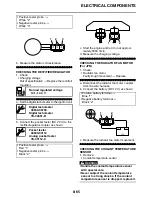
a. Connect the positive battery terminal “1” and
starter motor lead “2” with a jumper lead “3”.
EWA
WARNING
• Handle the coolant temperature sensor
with special care.
• Never subject the coolant temperature
sensor to strong shocks. If the coolant
temperature sensor is dropped, replace it.
b. Check the starter motor operation.
▲▲▲▲▲▲▲▲▲▲▲▲▲▲▲▲▲▲▲▲▲▲▲▲▲▲▲▲▲▲▲▲
EAS28150
CHECKING THE STATOR COIL
1. Disconnect:
• Stator coil coupler
(from the wire harness)
2. Check:
• Stator coil resistance
Out of specification
Replace the stator
coil.
▼▼▼▼▼▼▼▼▼▼▼▼▼▼▼▼▼▼▼▼▼▼▼▼▼▼▼▼▼▼▼▼
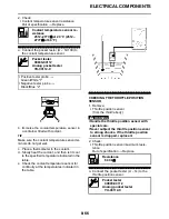
a. Connect the pocket tester (
1) to the sta-
tor coil coupler as shown.
Lean angle sensor output voltage
Operating angle
45 °
Output voltage up to operating
angle
3.6–4.4 V
Output voltage over operating an-
gle
0.3–1.4 V
Pocket tester
90890-03112
Analog pocket tester
YU-03112-C
Test harness-lean angle sensor
(6P)
90890-03209
YU-03209
• Positive tester probe
Yellow/Green “1”
• Negative tester probe
Black/Blue “2”
2
1
°
45
°
45
Stator coil resistance
0.528–0.792
(W–W)
Pocket tester
90890-03112
Analog pocket tester
YU-03112-C
• Positive tester probe
White “1”
• Negative tester probe
White “2”
• Positive tester probe
White “1”
• Negative tester probe
White “3”
Содержание YZ 2016 Series
Страница 6: ...EASB296006 YAMAHA MOTOR CORPORATION U S A YZ MOTORCYCLE LIMITED WARRANTY...
Страница 10: ......
Страница 31: ...CONTROL FUNCTIONS 1 19 a 2...
Страница 63: ...LUBRICATION POINTS AND LUBRICANT TYPES 2 22...
Страница 66: ...LUBRICATION SYSTEM CHART AND DIAGRAMS 2 25...
Страница 68: ...LUBRICATION SYSTEM CHART AND DIAGRAMS 2 27...
Страница 69: ...LUBRICATION SYSTEM CHART AND DIAGRAMS 2 28 1 Exhaust camshaft 2 Intake camshaft 3 Oil filter element 4 Oil pump...
Страница 70: ...LUBRICATION SYSTEM CHART AND DIAGRAMS 2 29...
Страница 71: ...LUBRICATION SYSTEM CHART AND DIAGRAMS 2 30 1 Camshaft 2 Oil pressure check bolt 3 Oil filter element 4 Oil pump...
Страница 72: ...CABLE ROUTING DIAGRAM 2 31 EASB296066 CABLE ROUTING DIAGRAM...
Страница 74: ...CABLE ROUTING DIAGRAM 2 33...
Страница 76: ...CABLE ROUTING DIAGRAM 2 35...
Страница 78: ...CABLE ROUTING DIAGRAM 2 37...
Страница 80: ...CABLE ROUTING DIAGRAM 2 39...
Страница 82: ...CABLE ROUTING DIAGRAM 2 41...
Страница 84: ...CABLE ROUTING DIAGRAM 2 43...
Страница 86: ...CABLE ROUTING DIAGRAM 2 45...
Страница 239: ...ELECTRIC STARTER 5 40 5 Install Bolt 1 O ring 2 TIP Apply the lithium soap based grease on the O ring New...
Страница 262: ...OIL PUMP AND BALANCER GEAR 5 63 a 2 10 b 2 9 1 b 5 3 a 4 10 5 9 3 E c d 6 7 8 8 b 6...
Страница 282: ...TRANSMISSION 5 83...
Страница 302: ...8 CHECKING THE INTAKE AIR TEMPERATURE SENSOR 8 68 CHECKING THE FUEL INJECTOR 8 68...
Страница 317: ...CHARGING SYSTEM 8 15...
Страница 321: ...COOLING SYSTEM For JPN 8 19...
Страница 351: ...FUEL PUMP SYSTEM 8 49...
Страница 352: ...ELECTRICAL COMPONENTS 8 50 EASB296346 ELECTRICAL COMPONENTS EASB296347 7 8 9 1 3 2 4 5 6...
Страница 354: ...ELECTRICAL COMPONENTS 8 52 11 10 9 2 3 1 6 7 8 4 5...
Страница 356: ...ELECTRICAL COMPONENTS 8 54 EASB296348 CHECKING THE SWITCHES 4 1 3 2 B B Sb B B B B B B B B...
Страница 357: ...ELECTRICAL COMPONENTS 8 55 1 Engine stop switch 2 Neutral switch 3 Clutch switch 4 Start switch...
Страница 378: ...LIST OF SELF DIAGNOSTIC AND FAIL SAFE ACTIONS 9 7...
Страница 392: ...ON OFF ON OFF Gy Gy B B Gy B B B L L B B B B B YZ250FXG 2016 WIRING DIAGRAM B29 28199 11_W D indd 2 2015 06 15 13 19 32...


