BASIC SERVICE INFORMATION
1-8
ECA
NOTICE
Handle electrical components with special
care, and do not subject them to strong
shocks.
ECA
NOTICE
Electrical components are very sensitive to
and can be damaged by static electricity.
Therefore, never touch the terminals and be
sure to keep the contacts clean.
TIP
Push and hold the engine stop switch to turn off
the engine when resetting the ECU (Electronic
Control Unit). Disconnect the starter motor lead
of the starter relay, and then push the starter
switch. Be sure to wait for five seconds or lon-
ger before pushing the start switch after the en-
gine is stopped.
Checking the electrical system
TIP
Before checking the electrical system, make
sure that the battery voltage is at least 12 V.
ECA
NOTICE
Never insert the tester probes into the cou-
pler terminal slots. Always insert the probes
from the opposite end “a” of the coupler,
taking care not to loosen or damage the
leads.
ECA
NOTICE
For waterproof couplers, never insert the
tester probes directly into the coupler.
When performing any checks using a water-
proof coupler, use the specified test har-
ness or a suitable commercially available
test harness.
a
Содержание YZ 2016 Series
Страница 6: ...EASB296006 YAMAHA MOTOR CORPORATION U S A YZ MOTORCYCLE LIMITED WARRANTY...
Страница 10: ......
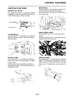
Страница 31: ...CONTROL FUNCTIONS 1 19 a 2...
Страница 63: ...LUBRICATION POINTS AND LUBRICANT TYPES 2 22...
Страница 66: ...LUBRICATION SYSTEM CHART AND DIAGRAMS 2 25...
Страница 68: ...LUBRICATION SYSTEM CHART AND DIAGRAMS 2 27...
Страница 69: ...LUBRICATION SYSTEM CHART AND DIAGRAMS 2 28 1 Exhaust camshaft 2 Intake camshaft 3 Oil filter element 4 Oil pump...
Страница 70: ...LUBRICATION SYSTEM CHART AND DIAGRAMS 2 29...
Страница 71: ...LUBRICATION SYSTEM CHART AND DIAGRAMS 2 30 1 Camshaft 2 Oil pressure check bolt 3 Oil filter element 4 Oil pump...
Страница 72: ...CABLE ROUTING DIAGRAM 2 31 EASB296066 CABLE ROUTING DIAGRAM...
Страница 74: ...CABLE ROUTING DIAGRAM 2 33...
Страница 76: ...CABLE ROUTING DIAGRAM 2 35...
Страница 78: ...CABLE ROUTING DIAGRAM 2 37...
Страница 80: ...CABLE ROUTING DIAGRAM 2 39...
Страница 82: ...CABLE ROUTING DIAGRAM 2 41...
Страница 84: ...CABLE ROUTING DIAGRAM 2 43...
Страница 86: ...CABLE ROUTING DIAGRAM 2 45...
Страница 239: ...ELECTRIC STARTER 5 40 5 Install Bolt 1 O ring 2 TIP Apply the lithium soap based grease on the O ring New...
Страница 262: ...OIL PUMP AND BALANCER GEAR 5 63 a 2 10 b 2 9 1 b 5 3 a 4 10 5 9 3 E c d 6 7 8 8 b 6...
Страница 282: ...TRANSMISSION 5 83...
Страница 302: ...8 CHECKING THE INTAKE AIR TEMPERATURE SENSOR 8 68 CHECKING THE FUEL INJECTOR 8 68...
Страница 317: ...CHARGING SYSTEM 8 15...
Страница 321: ...COOLING SYSTEM For JPN 8 19...
Страница 351: ...FUEL PUMP SYSTEM 8 49...
Страница 352: ...ELECTRICAL COMPONENTS 8 50 EASB296346 ELECTRICAL COMPONENTS EASB296347 7 8 9 1 3 2 4 5 6...
Страница 354: ...ELECTRICAL COMPONENTS 8 52 11 10 9 2 3 1 6 7 8 4 5...
Страница 356: ...ELECTRICAL COMPONENTS 8 54 EASB296348 CHECKING THE SWITCHES 4 1 3 2 B B Sb B B B B B B B B...
Страница 357: ...ELECTRICAL COMPONENTS 8 55 1 Engine stop switch 2 Neutral switch 3 Clutch switch 4 Start switch...
Страница 378: ...LIST OF SELF DIAGNOSTIC AND FAIL SAFE ACTIONS 9 7...
Страница 392: ...ON OFF ON OFF Gy Gy B B Gy B B B L L B B B B B YZ250FXG 2016 WIRING DIAGRAM B29 28199 11_W D indd 2 2015 06 15 13 19 32...

