USO
RESTRITO
Settings Relating to Function Links (Link Menu)
627
Knob
Parameter
Adjustment
Setting values
1
Link No
Link to which setting
applies
1 to 64
3
Link Table
No
Link table selection
1 to 8
Knob
Parameter
Adjustment
Setting values
3
Link Table
No
Link table
selection
1 to 8
Ch
a
p
te
r 20
S
wi
tc
h
e
r S
e
tu
p
(S
wi
tc
h
e
r)
5
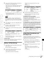
Using any of the following methods, select the bus to
be the link source, and press [Bus Set].
•
Press directly on the list appearing in the status area.
•
Press the arrow keys to scroll the reverse video
cursor.
•
Turn the knob.
Knob
Parameter
Adjustment
Setting values
2
No
Bus selection
1 to maximum
value
a)
a) Only when [Master Bus] is selected, M/E-1 to M/E-5 Trans PGM,
and P/P Trans PGM are available.
Only when [Linked Bus] is selected, AUX 1 to AUX 48 as Key are
available.
Notes
With one of M/E-1 to M/E-5 Trans PGM and P/P
Trans PGM selected for [Master Bus], the link setting
become effective as soon as you start moving the fader
lever.
6
In the <Bus Select> group, select [Linked Bus] (link
destination bus).
7
Referring to step
5
, select the bus to be the link
destination, and press [Bus Set].
8
Turn the knob to select the link table, and press [Link
Table Set].
•
Press the arrow keys to scroll the reverse video
cursor.
•
Turn the knobs.
Knob
Parameter
Adjustment
Setting values
4
Main No
Video/key signal
for link source
1 to 300
5
No
Video/key signal
for link
destination
1 to 300
3
To confirm the selection, press [Link Src Set].
This links the link destination signal to the signal
selected as Main No.
To initialize the set source address
In the Switcher >Link >Internal Bus Link >Link Table
Select menu, press [Init Link Table].
A confirmation message appears; press [Yes].
The source addresses are reassigned, and this is reflected
in the status area.
To change the link number and link table number
In the Switcher >Link >Internal Bus Link >Link Table
Select menu, you can also change the link number and link
table number. To do this, turn the knobs as follows to make
the setting, then press [Link Table Set].
For more information about link tables, see the
following item.
The selected link table number is confirmed, and this
is reflected in the status area.
To delete a link
Select the link you want to delete, then press [Clear] in the
Switcher >Link >Internal Bus Link menu.
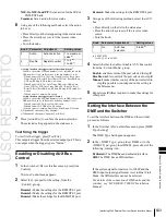
Making Link Table Settings
1
In the Switcher >Link >Internal Bus Link menu, press
[Link Table Select].
The Link Table Select menu appears.
2
Using any of the following methods, select the link
source and link destination signals.
•
Press directly on the list in the status area.
Linking Cross-Point Buttons and
GPI Output Ports
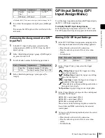
To link cross-point buttons or the [CUT] and [AUTO
TRANS] buttons in the cross-point control block, and GPI
output ports, use the following procedure.
1
In the Switcher >Link menu, press [GPI Link], to
display the Switcher >Link >GPI Link menu.
The status area shows the output ports and the link
status, and delay value information.
2
Using any of the following methods, select the GPI
output port.
•
Press directly on the list in the status area.
•
Press the arrow keys to scroll the reverse video
cursor.
•
Turn the knob.
Содержание MVS-8000X SystemMVS-7000X System
Страница 358: ...USO RESTRITO 358 Wipe Pattern List Appendix Volume 1 Enhanced Wipes Rotary Wipes ...
Страница 360: ...USO RESTRITO Random Diamond DustWipes 360 1 w pe PaternLO ...
Страница 362: ...USO RESTRITO 362 DME Wipe Pattern List Appendix Volume 1 Door 2D trans 3D trans ...
Страница 363: ...USO RESTRITO DME Wipe Pattern List 363 Appendix Volume 1 Flip tumble Frame in out Picture in picture ...
Страница 364: ...USO RESTRITO 364 DME Wipe Pattern List Appendix Volume 1 Page turn Page roll ...
Страница 365: ...USO RESTRITO DME Wipe Pattern List 365 Appendix Volume 1 Mirror Sphere Character trail Wave Ripple Split slide ...
Страница 367: ...USO RESTRITO DME Wipe Pattern List 367 Appendix Volume 1 Squeeze 3D trans Picture in picture Page turn ...
Страница 376: ...USO RESTRITO 376 Menu Tree Appendix Volume 1 Frame Memory Menu FRAME MEM button Color Bkgd Menu COLOR BKGD button ...
Страница 377: ...USO RESTRITO Menu Tree 377 Appendix Volume 1 AUX Menu AUX button CCR Menu CCR button ...
Страница 379: ...USO RESTRITO Menu Tree 379 Appendix Volume 1 DME Menu DME button ...
Страница 380: ...USO RESTRITO 380 Menu Tree Appendix Volume 1 Global Effect Menu GLB EFF button Router Menu Device Menu DEV button ...
Страница 381: ...USO RESTRITO Menu Tree 381 Appendix Volume 1 Macro Menu MCRO button ...
Страница 382: ...USO RESTRITO 382 Menu Tree Appendix Volume 1 Key Frame Menu KEY FRAME button ...
Страница 383: ...USO RESTRITO Menu Tree 383 Appendix Volume 1 Effect Menu EFF button ...
Страница 384: ...USO RESTRITO 384 Menu Tree Appendix Volume 1 Snapshot Menu SNAPSHOT button ...
Страница 385: ...USO RESTRITO Menu Tree 385 Appendix Volume 1 Shotbox Menu SHOTBOX button ...
Страница 386: ...USO RESTRITO 386 Menu Tree Appendix Volume 1 File Menu FILE button ...
Страница 388: ...USO RESTRITO 388 Menu Tree Appendix Volume 1 ENG SETUP button to previous page topages after 390 to next page ...
Страница 389: ...USO RESTRITO Menu Tree 389 Appendix Volume 1 ENG SETUP button to page 387 to previous pages to following pages ...
Страница 390: ...USO RESTRITO 390 Menu Tree Appendix Volume 1 ENG SETUP button to previous pages to next page a MVS 7000X only ...
Страница 391: ...USO RESTRITO Menu Tree 391 Appendix Volume 1 ENG SETUP button to previous pages ...
Страница 392: ...USO RESTRITO 392 Menu Tree Appendix Volume 1 User Setup Menu USER SETUP button Diagnostic Menu DIAG button ...
Страница 413: ...USO RESTRITO MVS 8000X System MVS 7000X System SY 4 470 637 01 1 Sony Corporation 2013 ...
Страница 706: ...USO RESTRITO MVS 8000X System MVS 7000X System SY 4 470 637 01 1 Sony Corporation 2013 ...


