USO
RESTRITO
Executing a Transition
105
Ch
a
p
te
r 3
S
ig
n
a
l S
e
le
c
ti
o
n
and
T
ra
n
s
itio
n
s
Executing a Transition
There are two modes of executing a transition: an auto
transition by button operation or a manual transition using
the fader lever.
It is also possible to combine both methods, taking control
with the fader lever of an auto transition which has partly
completed, or complete a transition started with the fader
lever as an auto transition.
By combining common transitions with independent key
transitions, different transition types can be applied to the
background and keys, for example allowing a key wipe
combined with a background dissolve.
When the audio mixer is linked in setup, you can carry out
an auto transition, and also switch the sound with the audio
mixer
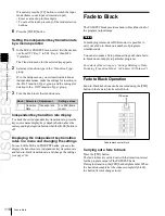
Transition Indicator Function
In each of the M/E banks and PGM/PST bank, to the left
of the fader lever is a transition indicator composed of
multiple LEDs. This indicator shows the state of the
transition, whether auto or manual, by which LEDs are lit.
You can also display the transition rate, independent key
transition rate, and fade-to-black transition rate for each of
the M/E and PGM/PST banks, and change the settings
Notes
When a clip transition is selected as the transition type, it
is not possible to set the transition rate.
Frame input mode and timecode input
mode
For numeric input of the transition rate value, there are two
modes: frame input mode and timecode input mode. You
select one of these modes using either the Flexi Pad control
block
, Multifunction Flexi Pad control block or
the numeric keypad control block
Frame input mode:
The entered value is a number of
frames.
Example: Entering 123 constitutes an entry of 123
frames
Timecode input mode:
The entered value is a timecode
value.
Example: Entering 123 constitutes an entry of 1
second 23 frames.
Notes
Whereas you can enter a value of up to 999 in frame input
mode, a value not smaller than 10 seconds cannot be
entered in timecode input mode.
Lit
Frame display mode and timecode display
mode
For the transition rate display in the transition control
block, there are two modes: frame display mode and
timecode display mode. You can select one of these modes
in setup.
For details, see “Setting the Transition Rate Display
Mode” in Chapter 19 (Volume 2).
Transition indicator
For example, in the previous illustration, it can be seen that
the transition is more than half completed.
When the transition is completed, all of the LEDs go off.
Setting the Transition Rate
There are two ways of setting the transition rate: using the
Flexi Pad control block, Multifunction Flexi Pad control
block or numeric keypad control block to enter a numeric
value, or using the Misc menu to access the Transition
menu for the M/E or PGM/PST bank.
Notes
The setting is common to all banks of the switcher.
Frame display mode:
Values are shown as from 0 to 999
frames. In this display mode, a value entered in
timecode input mode is converted for display as a
number of frames.
Timecode display mode:
Values are shown as timecode
values, consisting of seconds and frames. In this
display mode, a value entered in frame input mode is
converted for display as a timecode value. If the value
consists of four or more digits, the last digit is not
shown.
Содержание MVS-8000X SystemMVS-7000X System
Страница 358: ...USO RESTRITO 358 Wipe Pattern List Appendix Volume 1 Enhanced Wipes Rotary Wipes ...
Страница 360: ...USO RESTRITO Random Diamond DustWipes 360 1 w pe PaternLO ...
Страница 362: ...USO RESTRITO 362 DME Wipe Pattern List Appendix Volume 1 Door 2D trans 3D trans ...
Страница 363: ...USO RESTRITO DME Wipe Pattern List 363 Appendix Volume 1 Flip tumble Frame in out Picture in picture ...
Страница 364: ...USO RESTRITO 364 DME Wipe Pattern List Appendix Volume 1 Page turn Page roll ...
Страница 365: ...USO RESTRITO DME Wipe Pattern List 365 Appendix Volume 1 Mirror Sphere Character trail Wave Ripple Split slide ...
Страница 367: ...USO RESTRITO DME Wipe Pattern List 367 Appendix Volume 1 Squeeze 3D trans Picture in picture Page turn ...
Страница 376: ...USO RESTRITO 376 Menu Tree Appendix Volume 1 Frame Memory Menu FRAME MEM button Color Bkgd Menu COLOR BKGD button ...
Страница 377: ...USO RESTRITO Menu Tree 377 Appendix Volume 1 AUX Menu AUX button CCR Menu CCR button ...
Страница 379: ...USO RESTRITO Menu Tree 379 Appendix Volume 1 DME Menu DME button ...
Страница 380: ...USO RESTRITO 380 Menu Tree Appendix Volume 1 Global Effect Menu GLB EFF button Router Menu Device Menu DEV button ...
Страница 381: ...USO RESTRITO Menu Tree 381 Appendix Volume 1 Macro Menu MCRO button ...
Страница 382: ...USO RESTRITO 382 Menu Tree Appendix Volume 1 Key Frame Menu KEY FRAME button ...
Страница 383: ...USO RESTRITO Menu Tree 383 Appendix Volume 1 Effect Menu EFF button ...
Страница 384: ...USO RESTRITO 384 Menu Tree Appendix Volume 1 Snapshot Menu SNAPSHOT button ...
Страница 385: ...USO RESTRITO Menu Tree 385 Appendix Volume 1 Shotbox Menu SHOTBOX button ...
Страница 386: ...USO RESTRITO 386 Menu Tree Appendix Volume 1 File Menu FILE button ...
Страница 388: ...USO RESTRITO 388 Menu Tree Appendix Volume 1 ENG SETUP button to previous page topages after 390 to next page ...
Страница 389: ...USO RESTRITO Menu Tree 389 Appendix Volume 1 ENG SETUP button to page 387 to previous pages to following pages ...
Страница 390: ...USO RESTRITO 390 Menu Tree Appendix Volume 1 ENG SETUP button to previous pages to next page a MVS 7000X only ...
Страница 391: ...USO RESTRITO Menu Tree 391 Appendix Volume 1 ENG SETUP button to previous pages ...
Страница 392: ...USO RESTRITO 392 Menu Tree Appendix Volume 1 User Setup Menu USER SETUP button Diagnostic Menu DIAG button ...
Страница 413: ...USO RESTRITO MVS 8000X System MVS 7000X System SY 4 470 637 01 1 Sony Corporation 2013 ...
Страница 706: ...USO RESTRITO MVS 8000X System MVS 7000X System SY 4 470 637 01 1 Sony Corporation 2013 ...


