USO
RESTRITO
420
Control of GPI Devices
Ch
a
p
te
r 12
E
x
te
rn
a
l De
v
ic
e
s
Control of GPI Devices
You can control GPI devices from the control panel of this
system, or through the GPI output port of a DCU.
GPI timeline
For a keyframe effect controlled from the center control
panel, the GPI timeline allows you to set an action (setting
a trigger output from a particular GPI output port) at a
keyframe point on the GPI timeline. At any keyframe
point, you can make a maximum of eight GPI output port
settings.
GPI timeline actions
The actions that can be used on the GPI timeline are as
follows.
•
Control panel GPI output port
•
DCU GPI output port
For the GPI output settings (keyframe editing), use the
Device menu.
The data set in the Device menu is saved in a keyframe
effect register. When you recall this register and start
execution of the keyframe effect, and advance the effect to
the keyframe point for which the GPI output is set, a
trigger pulse is output to the external device from the
specified GPI output port.
GPI Timeline Creation and Editing
This section describes how to set GPI output ports to be
registered at a keyframe point, and how to carry out
creation and editing of the GPI timeline.
For details of keyframe creation and editing operations,
see “Creating and Editing Keyframes” (page 450).
GPI output port settings
Set the GPI output port number of the control panel or
DCU which outputs GPI pulses at a keyframe point on the
GPI timeline.
Use the following procedure. Use the same procedure to
subsequently change the settings.
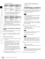
1
In the Device menu, press VF1 ‘GPI Timeline.’
The Device >GPI Timeline menu appears.
The status area shows the “GPI Output” list on the left
and the “GPI Port” list on the right.
The “GPI Output” list (on the left) shows the relation
between ports 1 to 8 for the GPI timeline and the
trigger pulse output destination ports. The content of
this list is saved as keyframe data.
The “GPI Port” list (on the right) is for selecting the
GPI trigger pulse output destination.
2
Using either of the following methods, select the GPI
timeline port you want to set on the GPI Timeline.
•
Press directly on the list on the left of the status area.
•
Turn the knob.
Knob
Parameter
Setting
Setting values
1
GPI Output
No
GPI timeline port
number
1 to 8
3
Using either of the following methods, trigger output
destination.
•
Press directly on the list on the right of the status
area.
•
Turn the knob.
Knob
Parameter
Setting
Setting values
2
GPI Port
No
SCU/DCU GPI
port to be the
trigger output
destination
1 to 3
a)
a) 1: Off (no specification)
2: Control panel (SCU) GPI port
3: DCU GPI port
4
If in step
3
you selected 2 (SCU) or 3 (DCU), then use
the knob to select the port number.
The indication for knob 3 depends on whether SCU or
DCU is selected.
Knob
Parameter
Setting
Setting values
3
SCU Port
No
SCU GPI port
number
1 to 8
3
DCU Port
No
DCU GPI port
number
1 to 50
a)
a) The number of DCU GPI ports depends on the settings in
Engineering Setup.
The setting is reflected in the list on the right of the
status area.
Notes
For the output port you have set here, be sure to set the
trigger type to “Rising Edge,” “Falling Edge” or “Any
Edge.”
For details of the trigger type settings, see “Making
Control Panel GPI Output Settings” (page 599) and
“Making DCU GPI Output Settings” (page 644).
5
Press [Set].
This specifies the SCU/DCU GPI port whose number
you specified in step
4
as the pulse output destination
Содержание MVS-8000X SystemMVS-7000X System
Страница 358: ...USO RESTRITO 358 Wipe Pattern List Appendix Volume 1 Enhanced Wipes Rotary Wipes ...
Страница 360: ...USO RESTRITO Random Diamond DustWipes 360 1 w pe PaternLO ...
Страница 362: ...USO RESTRITO 362 DME Wipe Pattern List Appendix Volume 1 Door 2D trans 3D trans ...
Страница 363: ...USO RESTRITO DME Wipe Pattern List 363 Appendix Volume 1 Flip tumble Frame in out Picture in picture ...
Страница 364: ...USO RESTRITO 364 DME Wipe Pattern List Appendix Volume 1 Page turn Page roll ...
Страница 365: ...USO RESTRITO DME Wipe Pattern List 365 Appendix Volume 1 Mirror Sphere Character trail Wave Ripple Split slide ...
Страница 367: ...USO RESTRITO DME Wipe Pattern List 367 Appendix Volume 1 Squeeze 3D trans Picture in picture Page turn ...
Страница 376: ...USO RESTRITO 376 Menu Tree Appendix Volume 1 Frame Memory Menu FRAME MEM button Color Bkgd Menu COLOR BKGD button ...
Страница 377: ...USO RESTRITO Menu Tree 377 Appendix Volume 1 AUX Menu AUX button CCR Menu CCR button ...
Страница 379: ...USO RESTRITO Menu Tree 379 Appendix Volume 1 DME Menu DME button ...
Страница 380: ...USO RESTRITO 380 Menu Tree Appendix Volume 1 Global Effect Menu GLB EFF button Router Menu Device Menu DEV button ...
Страница 381: ...USO RESTRITO Menu Tree 381 Appendix Volume 1 Macro Menu MCRO button ...
Страница 382: ...USO RESTRITO 382 Menu Tree Appendix Volume 1 Key Frame Menu KEY FRAME button ...
Страница 383: ...USO RESTRITO Menu Tree 383 Appendix Volume 1 Effect Menu EFF button ...
Страница 384: ...USO RESTRITO 384 Menu Tree Appendix Volume 1 Snapshot Menu SNAPSHOT button ...
Страница 385: ...USO RESTRITO Menu Tree 385 Appendix Volume 1 Shotbox Menu SHOTBOX button ...
Страница 386: ...USO RESTRITO 386 Menu Tree Appendix Volume 1 File Menu FILE button ...
Страница 388: ...USO RESTRITO 388 Menu Tree Appendix Volume 1 ENG SETUP button to previous page topages after 390 to next page ...
Страница 389: ...USO RESTRITO Menu Tree 389 Appendix Volume 1 ENG SETUP button to page 387 to previous pages to following pages ...
Страница 390: ...USO RESTRITO 390 Menu Tree Appendix Volume 1 ENG SETUP button to previous pages to next page a MVS 7000X only ...
Страница 391: ...USO RESTRITO Menu Tree 391 Appendix Volume 1 ENG SETUP button to previous pages ...
Страница 392: ...USO RESTRITO 392 Menu Tree Appendix Volume 1 User Setup Menu USER SETUP button Diagnostic Menu DIAG button ...
Страница 413: ...USO RESTRITO MVS 8000X System MVS 7000X System SY 4 470 637 01 1 Sony Corporation 2013 ...
Страница 706: ...USO RESTRITO MVS 8000X System MVS 7000X System SY 4 470 637 01 1 Sony Corporation 2013 ...

