Procedure
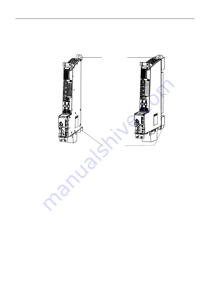
1. Mount the spacers on the control unit, if they have previously been removed.
2. Use two M6 screws to mount the control unit on the wall of the control cabinet (6 Nm
tightening torque).
0RXQWLQJZLWK
0VFUHZV
0RXQWLQJZLWK
0VFUHZV
&RROLQJULEV
([DPSOH''331
([DPSOH''331
Figure 3-2
Mounting of the D425‑2 DP/PN and D445‑2 DP/PN with spacers
Result
The control unit is arranged flush with the grouping on the wall of the control cabinet.
3.2.3
Mounting the SIMOTION D425-2 and D435-2 without spacers
The control units are supplied with pre-assembled spacers. For mounting without spacers,
proceed as follows:
1. Remove the upper and lower spacers (screws: M3, Torx T10)
2. There is a metal clip under the upper spacer; when shipped, the clip is pushed in and
secured with three screws (M3, Torx T10) fixed. Loosen the screws and push the clip up
until the upper hole extends beyond the housing.
Installing
3.2 Installing the SIMOTION D4x5-2
SIMOTION D4x5-2
38
Commissioning and Hardware Installation Manual, 03/2018, A5E33441636B


