&KDQQHOb
&KDQQHOb
&KDQQHOb
&KDQQHOb
QBVHW
QBDFW
LBDFW
,BVHW
QBVHW
LBDFW
QBDFW
7UDFH
UHFRUGHU
)XQFWLRQ
JHQHUDWRU
6SHHG
FRQWUROOHU
&XUUHQW
UHJXODWRU
&RQWUROOHG
V\VWHP
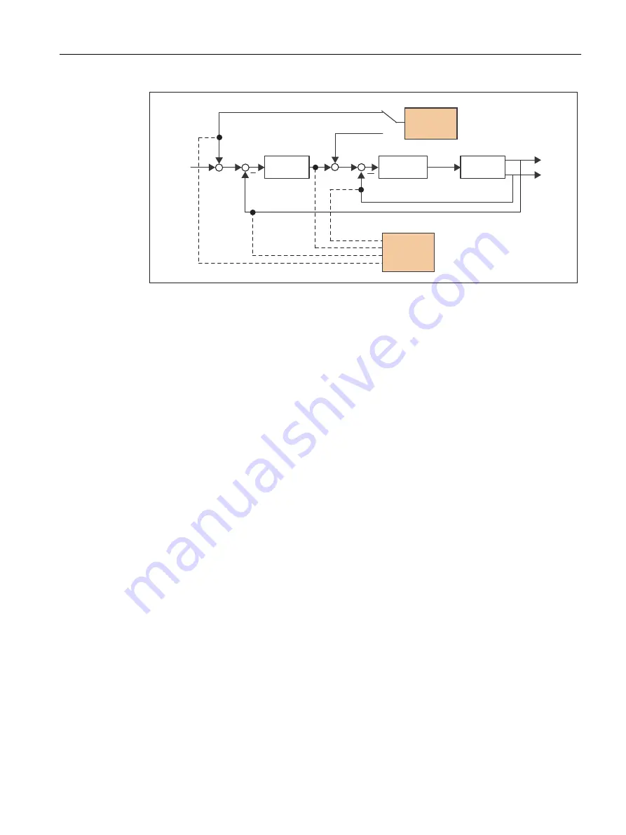
Figure 7-67
Optimizing a controller
Depending on the form of controller optimization to be performed, it is possible to define the
quality (e.g. signal form, amplitude, transient recovery time) of the disabled signal, the
measuring duration for step functions in the time range, or the bandwidth and number of
averaging operations in the frequency range for the trace. The analytical and graphical
evaluation can then be performed accordingly (FFT diagram, Bode diagram).
The following measuring functions are available:
● Setpoint jump at current controller
● Reference frequency response at current controller
● Setpoint jump at speed controller
● Disturbance variable jump at speed controller
● Reference frequency response at speed controller
● Disturbance frequency response at speed controller
● Speed-controlled system (input at current setpoint filter)
Additional references
For additional information about drive optimization, consult the
SINAMICS S120
Commissioning Manual.
Additional information on trace and measuring functions, as well as on the function generator,
can be found in the
SIMOTION SCOUT Online Help.
Commissioning (software)
7.16 Optimizing the drive and controller
SIMOTION D4x5-2
Commissioning and Hardware Installation Manual, 03/2018, A5E33441636B
305


