background image

Chapter 3: FRU Removal and Replacement Procedures

Replacing the Node Integrated Storage Controller Battery

Quantum DXi6900-S Field Service Manual

110


l

Replacing the Integrated Storage Controller Battery below

Obtaining a Replacement Integrated Storage Controller 
Battery

Before beginning the replacement procedure, make sure that you have the required replacement kit. The 
appropriate replacement integrated storage controller battery will be provided by Quantum Customer 
Support (see 

Figure 73 below

).

You will need the following items to perform this procedure:


l

Replacement integrated storage controller battery kit provided by Quantum Customer Support.


l

ESD grounding wrist strap (included in the replacement kit)
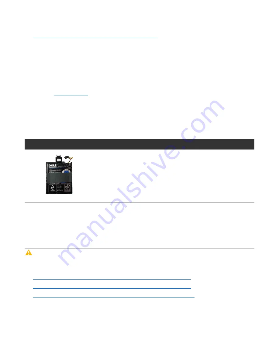
Figure 73: 

DXi6900-S Node Integrated Storage Controller Battery

Illustration

Description

Replacement battery for the integrated storage controller (Dell PERC H310)


Replacing the Integrated Storage Controller Battery

This section describes how to remove and replace the integrated storage controller battery in the DXi6900-
S Node.

Caution: 

Use appropriate ESD precautions, including the use of a grounding strap, when performing 

this procedure. 

Removing and replacing the integrated storage controller battery in the Node includes the following steps:


l

Identifying a Failed Integrated Storage Controller Battery on the next page


l

Removing a Failed Integrated Storage Controller Battery  on the next page


l

Installing a Replacement Integrated Storage Controller Battery on page 112

Содержание DXi6900-S

Страница 1: ...6 68448 05 DXi6900 S with DXi 3 4 0 Software Field Service Manual...

Страница 2: ...olation of the law TRADEMARK STATEMENT Artico Be Certain and the Q brackets design DLT DXi DXi Accent DXi V1000 DXi V2000 DXi V4000 GoVault Lattus NDX the Q logo the Q Quantum logo Q Cloud Quantum and...

Страница 3: ...ort Indicators 8 Node 10 GbE Ethernet Port Indicators 9 Node 10 GBaseT Ethernet Port Indicators 10 Node Power Supply Indicators 11 DXi6900 S Array and Expansion Modules 12 DXi6900 S Array and Expansio...

Страница 4: ...e iDRAC Port 29 Connecting to the System Node Using the Serial Port 31 Connecting to the System Node Using Santricity 31 Accessing the DXi6900 S Service Menu 32 Hardware Configuration Menu 32 Serial N...

Страница 5: ...iguring Continuous Replication 53 Retrieving a Crash Dump File 53 Accessing the Crash Dump File 54 Using WinSCP to Compress and Transfer the Crash Dump File 55 Transferring the Crash Dump File 57 Chap...

Страница 6: ...cement Integrated Storage Controller 105 Replacing the Integrated Storage Controller 106 Replacing the Node Integrated Storage Controller Battery 109 Obtaining a Replacement Integrated Storage Control...

Страница 7: ...xpansion Module 151 Installing a Replacement Drive in an Array or Expansion Module 152 Replacing Array or Expansion Module Power Supplies 153 Obtaining a Replacement Array or Expansion Power Supply 15...

Страница 8: ...Removing and Installing the PCIe Card Holder 177 Removing and Installing the Cable Retention Bracket 178 Removing and Installing the Information Tag 180 DXi6900 S Replacement Cables 183 Chapter 4 BIO...

Страница 9: ...Configuration l Web interface l Basic troubleshooting l Service menus and FRU replacement Audience This manual is written for Quantum DXi6900 S field service engineers Note It is useful for the audien...

Страница 10: ...sizes important information related to the main topic Caution Caution indicates potential hazards to equipment or data WARNING Warning indicates potential hazards to personal safety l Right side of th...

Страница 11: ...Preface Quantum DXi6900 S Field Service Manual xi Contacts For information about contacting Quantum including Quantum office locations go to http www quantum com aboutus contactus index aspx...

Страница 12: ...ts update contact information add attachments and receive status updates via email Online Service accounts are free from Quantum That account can also be used to access Quantum s Knowledge Base a comp...

Страница 13: ...S Field Service Manual xiii Worldwide End User Product Warranty For more information on the Quantum Worldwide End User Standard Limited Product Warranty http www quantum com serviceandsupport warrant...

Страница 14: ...cessing Remote Management 21 Locating DXi6900 S Serial Numbers 25 Basic Operations Overview This chapter describes the hardware features and basic operation of DXi6900 S systems and includes the follo...

Страница 15: ...ed on the front and back of each component l Node Front Panel Features and Indicators below l Node Rear Panel Connectors on page 4 l Node Solid State Drive Carrier Indicators on page 7 l Node 1 GbE Et...

Страница 16: ...Because of this you must unplug the Node before servicing Caution Turning off the power without properly shutting down the system may result in loss of data see Turning On and Shutting Down the Note T...

Страница 17: ...The ports are USB 2 0 compliant Caution Use of connected peripheral devices such as a USB keyboard and mouse or a VGA display is not supported and may cause incorrect system operation 10 NMI buttons N...

Страница 18: ...6900 S system This cable is compatible with Cisco 5000 Series Data Center Class switches The 10 GbE Copper Twinax cable options that Quantum provides do not support all switches Please note the suppor...

Страница 19: ...For data ingest read Ethernet or path to tape VTL ingest read Fibre Channel Table 2 on the next page lists all DXi6900 S configuration options 6 System identification button Press to toggle the syste...

Страница 20: ...Used 2 x 16 Gb Fibre Channel Not Used Not Used 2 x 16 Gb Fibre Channel 2 x 16 Gb Fibre Channel 2 x 16 Gb Fibre Channel 2 x 16 Gb Fibre Channel 2 x 16 Gb Fibre Channel 2 x 10 Gb Ethernet Not Used Not U...

Страница 21: ...ted failure l Blinks amber four times per second Drive failed l Blinks green slowly Drive rebuilding l Steady green Drive online l Blinks green three seconds amber three seconds and off six seconds Re...

Страница 22: ...e 1 GbE Ethernet Port LEDs 1 Link Indicator 2 Activity Indicator Node 10 GbE Ethernet Port Indicators Depending on the configuration Quantum DXi6900 S systems include a 10 GbE adapter card dual optica...

Страница 23: ...10 GBase T port on the DXi6900 S Node rear panel has two LED indicators see Figure 6 below Link indicator l Off Indicates the port is not connected to the network l Green Indicates the port is connect...

Страница 24: ...ed to the power supply and that the power supply is operational Flashing amber Indicates a problem with the power supply Flashing green When hot adding a power supply this indicates that the power sup...

Страница 25: ...ed to provide additional capacity backup data storage for the DXi6900 system Each DXi6900 S Array or Expansion module contains 12 drive carriers and provides 68 TB of licensable storage The DXi6900 S...

Страница 26: ...nd Expansion Module Front Panel Features and Indicators below l Array and Expansion Module Hard Drive Carrier Indicators on page 15 l Array Module Rear Panel Indicators on page 15 l Expansion Module R...

Страница 27: ...Item Button LED Description 1 Enclosure locate white Indicates the location of the enclosure within the system 2 Service action required amber Indicates at least one of the components within the enclo...

Страница 28: ...the array for service Drive fault amber Solid The hard drive has failed and a service ticket is created Contact Quantum customer support Blinking Drive volume or Array module locate function Drive ac...

Страница 29: ...13 14 15 16 17 18 19 1 1 2 2 3 3 3 4 4 Table 1 Array Module LEDs and Buttons Item Button LEDs Description 1 Ethernet link rate green Solid port speed 1000MB sec Off port speed 10 100MB sec 2 Ethernet...

Страница 30: ...quires attention Fault light will be on during power up and will turn off after self test sequence completes 9 Cache active green Solid unwritten data is stored in cache Blinking during AC power failu...

Страница 31: ...k ID Diag Port 1 ID Diag Port 1 ID Diag Port 1 1 2 3 4 5 6 7 8 9 10 11 12 13 1 1 2 2 Table 1 Expansion Module LEDs and Buttons Items Button LED Description 1 SAS host expansion fault amber Both Off ca...

Страница 32: ...ing applied to the ESM 8 Seven segment display green Displays tray ID and error code Displays 00 when the Array module is operating normally 9 Standby power green Solid main DC power is off and 5V sta...

Страница 33: ...3 below Wait until the seven segment display on the rear of the module displays 99 approximately 3 minutes 3 Press the power button on the front of the Node see Figure 14 on the next page Wait for the...

Страница 34: ...hut down 2 After the Node shuts down turn off both power switches on the back of each Array module RBOD Wait until the seven segment display on the rear of the module turns off 3 Turn off both power s...

Страница 35: ...s network access to the DXi6900 S 2 In the browser address box type the IP address of the DXi6900 S and then press Enter The Login window displays see Figure 15 below Figure 15 Login Window If the Log...

Страница 36: ...nagement console Password changes are not allowed Note Passwords are limited to 32 characters Alphanumeric characters and special characters are allowed Passwords can be changed on the Access Control...

Страница 37: ...ossible that one Administrator s changes will overwrite the other s Always coordinate configuration changes with other Administrator users Logging Off of the DXi6900 S When you are done working in the...

Страница 38: ...he system serial number the Node serial number and the Array and Expansion module serial numbers by looking at the physical components l The system serial number is located on the pull out information...

Страница 39: ...d Sources and Replication Streams 49 Configuring the Number of OST Replication Streams 51 Configuring Tag Retention and Continuous Replication 52 Retrieving a Crash Dump File 53 Service Menus Overview...

Страница 40: ...ds User Default Password Access Control Account Enabled Disabled Access root l Qa SmX7 DXi base software only install l Bs QwDa42 DXi after application software install Enabled after base only install...

Страница 41: ...o the System Node Using the iDRAC Port on the next page l Connecting to the System Node Using the Serial Port on page 31 l Connecting to the System Node Using Santricity on page 31 Note You can also d...

Страница 42: ...iDRAC main console which provides access to the root command prompt and the Service Menu The iDRAC main console also allows you to view the boot process and access the motherboard and RAID controller...

Страница 43: ...set by the customer DXi Administrator Note The iDRAC password changes as the ServiceLogin password is changed 5 Press Enter The iDRAC Main Console displays see Figure 20 below Figure 20 iDRAC Main Co...

Страница 44: ...laptop to the serial port on the Node see Figure 18 on page 28 2 Using a terminal emulation program that supports SSH like PuTTY connect to the Node using the following settings l Baud rate 115200 l D...

Страница 45: ...u displays see Figure 21 below Figure 21 Service Menu Service Menu 0 Hardware Configuration Tools for Configuring Hardware 1 Serial Numbers Tools for Node System and OUI Serial Numbers 2 Install Appli...

Страница 46: ...ge 35 l Factory Detect Hardware on page 37 l Encryption Tools on page 37 Setup IPMI Note In general you should not use the Setup IPMI menu to change IPMI settings as they are already configured at the...

Страница 47: ...y should not be used unless specifically directed by Engineering or ASPS Use the Internal RAID H730 Configuration Menu to create RAID sets on the disks in the system Node using the H730 controller The...

Страница 48: ...m for connected arrays 2 Locate an Array Locate an RBOD in the system 3 Add an Array Add an RBOD to the system 4 Add an EBOD to an Array Add an EBOD to an existing Array 5 Upgrade Array Firmware Downl...

Страница 49: ...rray modules Show Premium Feature Info Displays the Premium Feature Key PFK licenses installed on each Array module Upload Turbo PFK file Installs a Turbo Premium Feature Key PFK on the selected Array...

Страница 50: ...Menu type the option for Hardware Configuration and press Enter 3 From the Service Hardware Configuration Menu type the option for Factory Detect Hardware and press Enter to create a factory list of d...

Страница 51: ...ed Data at Rest license Creates a Data at Rest Recovery File that contains the encryption keys and passphrase Enable Disk Security Required Data at Rest license Enables Data at Rest Encryption using a...

Страница 52: ...ers The Serial Number Menu includes the following options Option Description Display All Numbers Displays all serial numbers associated with the hardware components of the DXi6900 S system Display Sys...

Страница 53: ...Service More Tools Menu 0 Reboot Node Reboot this Node 1 Collect Gather System information for Diagnostics 2 Array Collect Gather Array information for Diagnostics 3 Dell Collect Gather Dell s DSET i...

Страница 54: ...SET Report output file is located in root The file name includes the service tag of the Node and the date and time It takes up to 30 minutes or more to complete this collect Engineering Tools Includes...

Страница 55: ...ng the command line interface 1 Connect to the DXi6900 S Node see Connecting to the DXi6900 S Node on page 27 2 At the command prompt type the following command and press Enter cd opt DXi scripts 3 At...

Страница 56: ...load the system diagnostic log Collect Log Service Menu To gather a collect log using the Service Menu 1 Connect to the DXi6900 S Node see Connecting to the DXi6900 S Node on page 27 2 At the command...

Страница 57: ...er an unexpected shutdown due to a power loss During a blockpool verify operation the banner displays the Attention state Clicking Attention displays the message A previous unclean shutdown of the DXi...

Страница 58: ...to exit the status messages 4 If the blockpool verify has already completed and you want to see the log report type the following command and press Enter tail f var log blockpool_master log The follow...

Страница 59: ...erify Verify complete 5 Note the time when the blockpool verify completed Running the Blockpool Verification Script The blockpool verification script can be run during normal operations however it is...

Страница 60: ...BLOB tags can then be mapped back to VTL carts or NAS files using deduputil These carts or files are not able to be retrieved or replicated until repaired however they can be deleted If you see no co...

Страница 61: ...e everything has been repaired This can be achieved by verifying the individual BLOBs with hurricane blockpool bin blockpool verify tag Nlocal localhost Alternatively doing a full blob_data level veri...

Страница 62: ...lf the default number of streams that is 4 streams would result in approximately half the default replication performance Table 1 Maximum Allowed Replication Sources and Replication Streams Maximum Nu...

Страница 63: ...plied by the number of replication sources configured on the target must not exceed 90 Expressed as a formula MaxReplicationStreams on Source 1 x Number of Replication Sources Configured on Target 90...

Страница 64: ...se the number of Traditional Replication streams on the source system see Table 1 below Table 1 Maximum Traditional and OST Replication Streams Maximum Number of Traditional Replication Streams Maximu...

Страница 65: ...le change the variable MaxReplicationStreams to the new value 4 Reboot the source system using the Utilities Reboot Shutdown page in the remote management console Configuring OST Replication Streams T...

Страница 66: ...Replication By default continuous replication is enabled for shares or partitions that are configured for Directory File or Cartridge Based replication also called trigger replication Disabling contin...

Страница 67: ...UMP messages in the messages file to see if the crash dump file is available grep KDUMP var log messages Jul 02 11 43 48 Flames KDUMP CRIT KERNEL PANIC OOPS CRASH has occurred Jul 02 11 43 50 Flames K...

Страница 68: ...INFO Loading kdump kernel Success Jul 2 12 07 41 Flames KDUMP INFO waiting to mount snfs for 5 min Jul 2 12 10 53 Flames KDUMP INFO Waiting for linter database to start 60 sec Jul 2 12 14 20 Flames K...

Страница 69: ...to from folder Compressing the Crash Dump File Before you transfer the crash dump file to Quantum you must compress the file so it can be more easily transferred 1 Open a shell prompt to the DXi usin...

Страница 70: ...005_Flames_2009 07 02_11h43m48s tar bz2 Note The file size is approximately 2 GB to 30 GB compressed 32 GB to 128 GB uncompressed including log files for the DXi6900 S This process can take 30 45 minu...

Страница 71: ...ord see for system passwords Leave all other fields as defaults Note You can also leave the Username and Password boxes blank and you will be prompted to enter them during the authentication process A...

Страница 72: ...with the size of the file Figure 34 Progress Bar 4 After the copy has finished verify that it was successful by ensuring that the file is now present in the location specified and also by checking th...

Страница 73: ...plies 77 Replacing Node Cooling Fans 81 Replacing Node Memory Modules 84 Replacing Node CMOS Battery 89 Replacing Node Expansion Cards 93 Replacing the Node Integrated Storage Controller 105 Replacing...

Страница 74: ...eable Units and CRUs Customer Replaceable Units in the DXi6900 S are capable of being removed and replaced during normal system operation hot swappable Refer to Table 1 below to determine if a part is...

Страница 75: ...sink FRU No Yes Yes Solid State Drive Backplane FRU No Yes Yes System Board FRU No Yes Yes Node FRU No Yes Yes Node Chassis FRU No Yes Yes Array Module RBOD and Expansion Module EBOD Parts Hard Drive...

Страница 76: ...leave the Node in the rack you still must disconnect both power cables from the Node prior to opening the Node cover To remove the DXi6900 S Node from the rack and remove the top cover 1 Shut down the...

Страница 77: ...doffs 2 Rear rail J slots 3 Slide release lock button 4 Lock lever 5 Inner slide rails 6 Grasp the sides of the Node firmly and pull it forward until the rail standoffs are at the front of the J slots...

Страница 78: ...he Node for three seconds to fully drain the system of stored power prior to removing the cover see Figure 36 below Figure 36 Node Power Button 1 1 Power Switch 9 On the Node cover rotate the latch re...

Страница 79: ...r away from the Node 12 Remove the cooling shroud by holding the touch points and lifting the shroud away from the Node see Figure 38 below Note You do not need to remove the cooling shroud if you are...

Страница 80: ...S Field Service Manual 67 Figure 39 Removing the Cooling Fan Assembly 1 2 3 4 5 6 Item Description 1 Cooling fan assembly 2 Cooling fan 3 Release lever 2 4 Guide pin on the system board 2 5 Cooling f...

Страница 81: ...y slots with the guide pins on the chassis see Figure 40 below b Slide the cooling fan assembly into the chassis c Lock the cooling fan assemble into the chassis Figure 40 Replacing the Cooling Fan As...

Страница 82: ...1 Latch release lock 2 Latch 3 Node cover 4 Place the cover onto the Node chassis and offset the cover slightly back so that it clears the chassis hooks and lays flush on the chassis 5 Push down the l...

Страница 83: ...rail J slots 3 Slide release lock button 4 Lock lever 5 Inner slide rails 8 Locate the rear rail standoff on each side of the system and lower them into the rear J slots on the slide assemblies 9 Rot...

Страница 84: ...On the DXi6900 S on page 20 14 If applicable replace the front bezel Insert the right side of the bezel into the slots on the right side of the Node then snap the left side of the bezel into place In...

Страница 85: ...Hard drive backplane Replacing Node Solid State Drives This section describes how to remove and replace solid state drives SSDs in th Node and contains the following sections l Obtaining a Replacement...

Страница 86: ...Node 2 5 inch 960 GB SSD Replacing a Node Solid State Drive This section describes how to remove and replace a drive in the DXi6900 S Node Solid State drives are pre assembled in hot pluggable drive c...

Страница 87: ...LED Indicator Activity Drive activity indicator green l Flashing Indicates hard disk drive activity Drive status indicator green and amber l Off Drive ready for insertion or removal Note The drive st...

Страница 88: ...m the Node To remove the failed solid state drive from the DXi6900 S Node Caution You must replace the drive within three minutes after removal to prevent the possibility of overheating the equipment...

Страница 89: ...ling a Node Drive 1 2 3 Item Description 1 Release button 2 Drive handle 3 Drive carrier Installing a Replacement Drive in the Node To install the replacement solid state drive in the DXi6900 S Node C...

Страница 90: ...se the DXi6900 S normally while the drive rebuilds System performance may be reduced during the rebuilding process 4 If necessary replace the front bezel on the Node 5 In the remote management console...

Страница 91: ...te management console Caution Use appropriate ESD precautions including the use of a grounding strap when performing this procedure Removing and replacing a power supply in the Node includes the follo...

Страница 92: ...re hot swappable When replacing power supplies never remove more than one power supply at a time from the system Also before you remove one power supply make sure the other power supply is operating c...

Страница 93: ...S Node 1 Slide the replacement power supply into the chassis until the power supply is fully seated and the release latch snaps into place see Figure 51 above 2 Connect the power cable to the power su...

Страница 94: ...ou will need the following items to perform this procedure l Replacement cooling fan kit provided by Quantum Customer Support l ESD grounding wrist strap included in the replacement kit Figure 52 DXi6...

Страница 95: ...cooling fan 1 Access the remote management console see Accessing Remote Management on page 21 2 Navigate to the Status Hardware Details System Board page 3 Note the number 1 6 of the cooling fan that...

Страница 96: ...igure 54 below Figure 54 Removing and Installing a Cooling Fan 1 2 3 4 5 Item Description 1 Cooling fan assembly 2 Cooling fan connector 3 Fan release tab 4 Cooling fan 5 Cooling fan connector Install...

Страница 97: ...odule below Obtaining a Replacement Node Memory Module Before beginning the replacement procedure make sure that you have the required replacement kit The appropriate replacement memory module will be...

Страница 98: ...Only 8 or 16 of the 24 memory sockets are populated with memory modules depending on the configuration see Table 1 below and Figure 56 on the next page Note Memory socket numbers are displayed on the...

Страница 99: ...DXi6900 S Node Memory Module Locations 1 To identify the memory socket containing the failed DIMM 1 Log on to the remote management console as the service user see Accessing Remote Management on page...

Страница 100: ...below Figure 57 Identifying a Failed Memory Module 7 Check the DSET report entries for DIMM sockets A1 A8 and B1 B8 to locate the failed DIMM Removing a Failed Memory Module from the Node To remove th...

Страница 101: ...emory module in the DXi6900 S Node Caution Handle the memory modules by the card edges and avoid touching the components on the memory module 1 Align the memory module s edge connector with the alignm...

Страница 102: ...value is less than expected one or more of the memory modules may not be installed properly Shut down the DXi6900 S then repeat this procedure checking to ensure that the memory modules are firmly sea...

Страница 103: ...emoving and replacing a CMOS battery the Node includes the following steps l Identifying a Failed CMOS Battery below l Removing a Failed CMOS Battery from the Node on the next page l Installing a Repl...

Страница 104: ...60 Checking CMOS Battery Status Removing a Failed CMOS Battery from the Node To remove the failed CMOS battery from the DXi6900 S Node 1 Shut down the system see Turning Off the DXi6900 S on page 21...

Страница 105: ...n the positive side of the connector see on page 89 5 Lift the battery out of the securing tabs at the negative side of the connector Installing a Replacement CMOS Battery in the Node To install the r...

Страница 106: ...DXi6900 S BIOS Settings on page 184 8 Navigate to the Configuration System Date Time page to enter the correct time and date 9 In the remote management console delete any administrative alerts and clo...

Страница 107: ...Expansion card riser 1 accommodates low profile PCIe cards while expansion card riser 2 and 3 accommodate standard height PCIe cards Figure 63 DXi6900 S Node Expansion Card Locations 1 2 3 Item Descri...

Страница 108: ...P Ethernet ports l Dual port 10 GBase T Ethernet port l Dual port 16 Gb Fibre Channel See Table 2 below for DXi6900 S card configuration options Table 2 DXi6900 S PCI Slot Configuration Options Cautio...

Страница 109: ...rd Before beginning the replacement procedure make sure that you have the required replacement kit The appropriate replacement expansion card will be provided by Quantum Customer Support see Figure 64...

Страница 110: ...al port 12 Gb SAS card Dell Slot 3 bottom Dual port 12 Gb SAS card Dell Caution Use appropriate ESD precautions including the use of a grounding strap when performing this procedure Removing and repla...

Страница 111: ...vice Manual 98 4 Holding the touch points lift the expansion card riser 1 from the riser connector on the system board see Figure 65 below Figure 65 Removing and Installing the Expansion Card Riser 1...

Страница 112: ...iser left 5 Expansion card riser 1 connector 6 Front riser guide 7 Touch points 5 Press tab A and rotate the latch clockwise see Figure 66 below 6 Press tab B and rotate the latch down 7 Remove the ex...

Страница 113: ...il the card is fully seated 3 Close the expansion card latches 4 If applicable connect any cables to the expansion card 5 Install the expansion card riser see Figure 65 on page 98 6 Close the Node cov...

Страница 114: ...rt 16 Gb Fibre Channel QLogic See Table 2 on page 95 for DXi6900 S card configuration options Caution Use appropriate ESD precautions including the use of a grounding strap when performing this proced...

Страница 115: ...Node Expansion Cards Quantum DXi6900 S Field Service Manual 102 Figure 67 Removing and Installing the Expansion Card Riser 2 1 2 3 4 5 Item Description 1 Power connector 2 Expansion card riser 2 3 Ba...

Страница 116: ...and Installing the Expansion Card Riser 3 1 2 3 4 5 Item Description 1 Front riser 2 Power connector 3 Expansion card riser 3 4 Back riser 5 Expansion card riser 3 connector 5 Lift the expansion card...

Страница 117: ...rvice Manual 104 Figure 69 Removing and Installing an Expansion Card in Riser 2 or 3 1 2 3 4 5 Item Description 1 Expansion card 2 Latch 3 Expansion card riser 4 Power connector 5 Expansion card conne...

Страница 118: ...re see Factory Detect Hardware on page 37 9 In the remote management console delete any administrative alerts and close any service tickets Note Installation of new Fibre Channel cards will change the...

Страница 119: ...entifying a Failed Integrated Storage Controller below l Removing a Failed Integrated Storage Controller on the next page l Replacing the Node Integrated Storage Controller on the previous pageInstall...

Страница 120: ...DXi6900 S on page 21 2 Remove the Node cover see Opening and Closing the Node on page 63 3 Remove the expansion card riser 1 see Replacing an Expansion Card in Riser 1 on page 97 4 Loosen the screws...

Страница 121: ...Xi6900 S Field Service Manual 108 Figure 72 Removing and Installing the Integrated Storage Controller Card 1 2 3 4 Item Description 1 Integrated storage controller cable 2 Integrated storage controlle...

Страница 122: ...63 7 Verify the RAID BIOS settings on the replacement PERC H730 a Turn on the system see Turning On the DXi6900 S on page 20 b During the boot process press Ctrl R when prompted to enter the PERC H73...

Страница 123: ...r Support l ESD grounding wrist strap included in the replacement kit Figure 73 DXi6900 S Node Integrated Storage Controller Battery Illustration Description Replacement battery for the integrated sto...

Страница 124: ...ment on page 21 2 Navigate to the Status Hardware Details Storage Arrays page 3 Under Storage Arrays click a0 and then click Batteries and note the PERC H730 battery status below see Figure 74 below F...

Страница 125: ...rn on the system see Turning On the DXi6900 S on page 20 5 Run Factory Detect Hardware from the Service Menu to detect the new hardware see Factory Detect Hardware on page 37 6 In the remote managemen...

Страница 126: ...hen performing this procedure Removing and replacing the network daughter card in the Node includes the following steps l Identifying a Failed Network Daughter Card below l Removing a Failed Network D...

Страница 127: ...page 63 3 Remove the quad port SAS card in expansion card riser 2 see Replacing an Expansion Card in Riser 2 or 3 on page 100 4 Using a 2 Phillips screwdriver loosen the two captive screws that secur...

Страница 128: ...Network Daughter Card Quantum DXi6900 S Field Service Manual 115 Figure 78 Removing and Installing the Network Daughter Card 1 2 3 4 1 2 3 4 5 6 Item Description 1 Captive screw sockets 2 Connector on...

Страница 129: ...or 3 on page 100 6 Close the Node cover see Opening and Closing the Node on page 63 7 Turn on the system see Turning On the DXi6900 S on page 20 8 Run Factory Detect Hardware from the Service Menu to...

Страница 130: ...p when performing this procedure Removing and replacing the processor and heatsink in the Node includes the following steps l Identifying a Failed Processor and Heatsink below l Removing a Failed Heat...

Страница 131: ...ed down Allow the heatsink and processor to cool before handling them 1 Shut down the system see Turning Off the DXi6900 S on page 21 2 Remove the Node cover see Opening and Closing the Node on page 6...

Страница 132: ...the Processor Heatsink 1 2 3 4 Item Description 1 Captive screw 4 2 Heat sink 3 Processor socket 4 Captive screw socket 4 Removing a Failed Processor Caution The processor is held in its socket under...

Страница 133: ...he locked position by pushing down and out from under the tab Rotate the lever 90 degrees upward Figure 82 Processor Shield Opening and Closing Lever Sequence 1 2 3 4 5 Item Description 1 Close first...

Страница 134: ...n antistatic container for reuse return or temporary storage Do not touch the bottom of the processor Touch only the side edges of the processor Figure 83 Removing and Installing a Processor 1 2 3 4 5...

Страница 135: ...ar the unlock icon until it is locked in position 6 Using a clean lint free cloth remove the thermal grease from the heatsink Caution Applying too much thermal grease can result in excess grease comin...

Страница 136: ...erform this procedure l Replacement solid state drive backplane kit provided by Quantum Customer Support l Masking tape and felt tip marker for temporarily labeling drives l ESD grounding wrist strap...

Страница 137: ...e Cooling Fan Assembly on page 175 4 Remove all drives see Replacing a Node Solid State Drive on page 73 Caution To prevent damage to the drives and backplane you must remove the drives from the syste...

Страница 138: ...antum DXi6900 S Field Service Manual 125 Item Description 1 Drive backplane assembly 2 Backplane signal cable 3 Backplane power cable 4 Release tab 2 5 SAS cable 2 6 Mini SAS connector 7 Solid state d...

Страница 139: ...n assembly see Removing and Installing the Cooling Fan Assembly on page 175 5 Install the drives in their original locations see Replacing a Node Solid State Drive on page 73 Caution You must install...

Страница 140: ...t kit Figure 87 DXi6900 S Node System Board Illustration Description Replacement system board Replacing the System Board This section describes how to remove and replace the system board in the DXi690...

Страница 141: ...ted Storage Controller on page 106 e PCIe card holder see Removing and Installing the PCIe Card Holder on page 177 f Cable retention bracket see Removing and Installing the Cable Retention Bracket on...

Страница 142: ...5 Disconnect all cables from the system board 6 Grasp the system board holder lift the blue release pin and slide the system board toward the front of the system see Figure 89 on the next page Cautio...

Страница 143: ...ption 1 Release pin 2 System board 3 System board holder 7 Remove the heatsinks and processors see Replacing the Processor and Heatsink on page 117 WARNING The heatsink and processor are hot to the to...

Страница 144: ...able Retention Bracket on page 178 b PCIe card holder see Removing and Installing the PCIe Card Holder on page 177 c Integrated storage controller card see Replacing the Integrated Storage Controller...

Страница 145: ...ble on the DXi6900 S downloads page on https csweb quantum com l 82DFV_R720_CustBSU pm file available on the DXi6900 S downloads page on https csweb quantum com Installing the Service Tag To install t...

Страница 146: ...pdated BIOS splash logo displays Verifying iDRAC Settings After replacing the system board you must verify that certain iDRAC settings are set to the Quantum required value and make any changes as nee...

Страница 147: ...ment Node will be provided by Quantum Customer Support see Figure 90 below You will need the following items to perform this procedure l Replacement Node kit provided by Quantum Customer Support l Mas...

Страница 148: ...llation and Upgrade Guide and the customer data currently on the system will be lost Caution Use appropriate ESD precautions including the use of a grounding strap when performing this procedure Remov...

Страница 149: ...page 20 5 Run Factory Detect Hardware from the Service Menu to detect the new hardware see Factory Detect Hardware on page 37 6 Install the original system serial number on the new Node Note The syste...

Страница 150: ...included in the replacement kit Figure 92 DXi6900 S Node Chassis Illustration Description Replacement Node chassis Replacing the Node Chassis This section describes how to remove and replace the DXi69...

Страница 151: ...ated storage controller card see Replacing the Integrated Storage Controller on page 106 e PCIe card holder see Removing and Installing the PCIe Card Holder on page 177 f Cable retention bracket see R...

Страница 152: ...ard 7 Grasp the system board holder lift the blue release pin and slide the system board toward the front of the system see Figure 94 on the next page Caution Take care not to damage the system identi...

Страница 153: ...Installing the System Board 1 2 3 Item Description 1 Release pin 2 System board 3 System board holder Installing a Replacement Node Chassis To install the replacement DXi6900 S Node chassis 1 Install...

Страница 154: ...tion bracket see Removing and Installing the Cable Retention Bracket on page 178 d PCIe card holder see Removing and Installing the PCIe Card Holder on page 177 e Integrated storage controller card se...

Страница 155: ...n page 152 Note DXi6900 S hard disk drives are hot swappable You do not need to shut down the system to remove and replace a drive Caution Powering down the system incorrectly or removing the wrong dr...

Страница 156: ...aution Do not remove a hard drive that has not failed Instead only remove a drive that has failed If you accidently remove a good drive wait 30 seconds before reinserting the drive Caution Use appropr...

Страница 157: ...rray2 corresponds to RBOD2 b To view the hard drives within a specific array click Qarray1 for the first array and Qarray2 for the second array The Expansion modules are listed under the Array modules...

Страница 158: ...Designations Rack Expansion Module 2 3 Qarray 2 Tray 3 Expansion Module 2 2 Qarray 2 Tray 2 Expansion Module 2 1 Qarray 2 Tray 1 Array Module 2 Qarray 2 Tray 99 Node Redundant Power Supply and blanko...

Страница 159: ...e hard drive has failed l Blinking Drive volume or Array module locate function Drive active LED green l Solid No activity on the hard drive l Blinking There is activity on the hard drive Note If a dr...

Страница 160: ...e These IDs are required for the CLI command 2 Connect to the system node see Connecting to the DXi6900 S Node on page 27 The command prompt displays 3 Enter the following CLI command at the command p...

Страница 161: ...city Application 3 Click on the Qarray to view The Santricity Array Management appears see Figure 102 below Figure 102 Santricity Array Management 4 In the Hardware tab Santricity displays the drives...

Страница 162: ...n page 145 and DXi6900 S Array and Expansion Module Drive Slot Numbering on page 146 for location and designations of the array modules and expansion modules SMcli n Qarray1a p Qa Ar39 c set drive Tra...

Страница 163: ...ck on the Hardware menu option Use the keyboard arrow keys to select Drive Advanced Fail see Figure 103 below Figure 103 Santricity Drive Fail The Confirm Fail Drive dialog box opens see Figure 104 be...

Страница 164: ...LED will light see Figure 100 on page 146 11 Remove and replace the failed drive see Removing a Drive from an Array or Expansion Module below Removing a Drive from an Array or Expansion Module To remo...

Страница 165: ...talling a drive always place your hand under the drive to support its weight 1 Carefully unpack the replacement drive and set it on a dry level surface near the Array module or Expansion module 2 On t...

Страница 166: ...ty indicator for all drives in the Array module or Expansion module will blink green while the drive is rebuilding l The rebuild process takes approximately 17 hours no system load to 23 hours normal...

Страница 167: ...upply Illustration Description Replacement power supply for DXi6900 S Array module RBOD or Expansion module EBOD 585 watt Replacing an Array or Expansion Power Supply This section describes how to rem...

Страница 168: ...Module Power Supplies Use the indicator LEDs on the power supply to identify the failed power supply see Figure 110 below Standby power solid green Main DC power is off and 5V standby power is on DC...

Страница 169: ...oss may occur 1 Disconnect the power cable from the power source and the failed power supply see Figure 111 below 2 Pull the handles out and toward the sides of the power supply 3 Slide the power supp...

Страница 170: ...tion describes how to remove and replace a controller in a DXi6900 S Array module RBOD and contains the following sections l Obtaining a Replacement Array Module Controller below l Replacing an Array...

Страница 171: ...controller includes the following steps l Identifying a Failed Array Module Controller below l Removing a Failed Array Module Controller on page 160 l Installing a Replacement Array Module Controller...

Страница 172: ...failed controller on the back of the Array module by viewing the Service Action LEDs see Figure 114 below Figure 114 Array Module Controller Failure LEDs Service Action Description Service Action Req...

Страница 173: ...ontroller air blocker by removing it from the packaging and folding it inward at right angles so it is ready to insert into the open controller slot see Figure 115 below Figure 115 Controller Air Bloc...

Страница 174: ...eplacing an Array Module BBU on the next page 2 Remove the controller air blocker from the controller slot 3 Slide the replacement Array module controller into the empty bay until the controller snaps...

Страница 175: ...cement kit The appropriate Array module BBU will be provided by Quantum Customer Support see Figure 117 below You will need the following items to perform this procedure l Replacement Array module BBU...

Страница 176: ...controller contains a battery backup unit BBU To identify the Array module controller with the failed BBU 1 Access the remote management console see Accessing Remote Management on page 21 2 Navigate...

Страница 177: ...his LED is lit when the component has failed but it is not yet in a state to be replaced Service Action Allowed This LED is lit when the component has failed and is ready to be replaced Removing a Fai...

Страница 178: ...les from the controller with the failed BBU 3 Pull the handles out and toward the sides of the controller canister and pull the Array module controller out of the Array module chassis see Figure 121 b...

Страница 179: ...and remove the battery Installing a Replacement Array Module BBU To install the replacement Array module BBU 1 Insert the new battery by sliding it towards the front of the controller canister see Fig...

Страница 180: ...37 9 In the remote management console delete any administrative alerts and close any service tickets Replacing an Expansion Module ESM Canister This section describes how to remove and replace the ESM...

Страница 181: ...steps l Identifying a Failed Expansion Module ESM below l Removing a Failed Expansion Module ESM on page 170 l Installing a Replacement Expansion Module ESM on page 170 Identifying a Failed Expansion...

Страница 182: ...ed ESM canister on the back of the Expansion module by viewing the Service Action LEDs see Figure 125 below Figure 125 Expansion Module ESM Canister Failure LEDs Service Action Description Service Act...

Страница 183: ...r 1 Slide the replacement Expansion module ESM canister into the empty bay until the canister snaps into place and push the handles into the closed position see Figure 126 above 2 Connect the SAS cabl...

Страница 184: ...EBOD chassis and contains the following sections l Obtaining a Replacement Array or Expansion Module Chassis below l Replacing the Array or Expansion Module Chassis on the next page Obtaining a Repla...

Страница 185: ...ding the use of a grounding strap when performing this procedure Removing and replacing the DXi6900 S Array module or Expansion module chassis includes the following steps l Removing a Failed Array or...

Страница 186: ...tion You must note the number of each hard drive and temporarily label them before removal so that you can install each of them in the correct location in the replacement Array module or Expansion mod...

Страница 187: ...cement chassis see Replacing an Expansion Module ESM Canister on page 168 Caution Make sure to install the controllers or ESM canisters in the correct bay Install controller canister A in the left bay...

Страница 188: ...Card Holder on page 177 l Removing and Installing the Cable Retention Bracket on page 178 l Removing and Installing the Information Tag on page 180 Removing and Installing the Cooling Fan Assembly To...

Страница 189: ...res Quantum DXi6900 S Field Service Manual 176 1 2 3 4 5 6 Item Description 1 Cooling fan assembly 2 Cooling fan 3 Release lever 2 4 Guide pin on the system board 2 5 Cooling fan connector 6 6 Guide p...

Страница 190: ...ling fan assembly into the chassis 3 Lock the cooling fan assembly into the chassis by rotating the blue release levers downward until firmly seated Removing and Installing the PCIe Card Holder To rem...

Страница 191: ...page Removing and Installing the Cable Retention Bracket To remove and replace the cable retention bracket refer to the following procedures l Removing the Cable Retention Bracket below l Replacing th...

Страница 192: ...Cable Retention Bracket 1 2 3 Item Description 1 Alignment pins 2 Tab 3 Cable retention bracket Replacing the Cable Retention Bracket To replace the cable retention bracket 1 Using alignment pins as g...

Страница 193: ...s and the replacement Node chassis l Removing the Information Tag below l Replacing the Information Tag on page 182 Removing the Information Tag To remove the information tag 1 Using a 2 Phillips scre...

Страница 194: ...val and Replacement Procedures Additional Removal and Replacement Procedures Quantum DXi6900 S Field Service Manual 181 Figure 132 Removing and Installing the Control Panel 1 2 3 4 5 6 Item Descriptio...

Страница 195: ...it from the control panel Figure 133 Removing and Installing the Information Tag EST 1 2 3 Item Description 1 Information tag 2 Tabs 3 Slot Replacing the Information Tag To replace the information ta...

Страница 196: ...system is running data may be lost Table 1 DXi6900 S Replacement Cables Part Number Description 8 01345 11 Replacement 12 Gb SAS cable 1 meter 9 02033 01 Replacement 1 GbE Ethernet cable 25 feet 9 02...

Страница 197: ...oard in the Node After replacing the system board the BIOS is automatically updated to the correct Quantum version when the system boots up There is no need to manually update the BIOS After replacing...

Страница 198: ...To verify iDRAC BIOS settings are correct see Verifying iDRAC Settings Table 1 DXi6900 S Required BIOS Settings BIOS Field Name Values Default First Quantum Required Value Memory Settings System Memor...

Страница 199: ...Number of Cores per Processor All 1 2 4 6 All Processor 64 bit Support Yes Yes Processor Core Speed 2 50 GHz 2 50 GHz Processor Bus Speed 9 60 GT s 9 60 GT s Processor 1 and 2 Family Model Stepping 0...

Страница 200: ...1 Enabled Disabled OS Enabled OS Watchdog Timer Disabled Enabled Disabled I OAT DMA Engine Disabled Enabled Disabled Embedded Video Controller Enabled Disabled Enabled Current State of EVC Enabled Di...

Страница 201: ...VT220 ANSI ANSI omconfig chassis biossetup attribute ConTermType setting Ansi Redirection After Boot Enabled Disabled Enabled System Profile Settings System Profile Performance Per Watt DAPC Performan...

Страница 202: ...User Defined Delay 60s to 240s 60 240 sec 60 Miscellaneous Settings System time Set to current time Set to current time System Date Set to current date Set to current date Asset Tag Keyboard NumLock O...

Страница 203: ...S SAS Cabling Node to RBODs on the next page l Figure 135 on the next page DXi6900 S SAS Cabling RBODs to EBODs on the next page l Figure 136 on page 193 DXi6900 S SAS Cabling EBODs 1 1 through 1 3 o...

Страница 204: ...ield Service Manual 191 Figure 134 DXi6900 S SAS Cabling Node to RBODs Port 1 Port 2 ID Diag O O Port 1 Port 2 ID Diag O O Port 1 Port 2 ID Diag O O Port 1 Port 2 ID Diag O O System Node RBOD 1 RBOD 2...

Страница 205: ...tum DXi6900 S Field Service Manual 192 ID Diag Port 1 ID Diag Port 1 Port 1 Port 2 ID Diag O O Port 1 Port 2 ID Diag O O RBOD 2 EBOD 2 1 1A 1B 1A 1B ID Diag Port 1 ID Diag Port 1 Port 1 Port 2 ID Diag...

Страница 206: ...D Diag Port 1 ID Diag Port 1 EBOD 1 3 ID Diag Port 1 ID Diag Port 1 EBOD 1 2 EBOD 1 1 ID Diag Port 1 ID Diag Port 1 1A 1B 1A 1B 1A 1B 1A 1B 1A 1B Figure 137 DXi6900 S SAS Cabling EBODs 2 1 through 2 3...

Страница 207: ...or 2 ID Diag Port 1 ID Diag Port 1 EBOD 0 to 13 Port 1 Port 2 ID Diag O O Port 1 Port 2 ID Diag O O Primary AC Source Secondary AC Source Primary AC Source Secondary AC Source Primary AC Source Secon...

Страница 208: ...0 S Cabling Diagrams Quantum DXi6900 S Field Service Manual 195 Figure 140 DXi6900 S Ethernet Cabling 1 2 3 4 Item Description 1 To 1 GbE network 2 To 10 GbE network optional 3 To 10 GbE network optio...

Отзывы: