background image

— A-17 — 


B

B

3

3


t

t

y

y

p

p

e

e


B

B

5

5


t

t

y

y

p

p

e

e


2

2

3

3


t

t

y

y

p

p

e

e


2

2

5

5


t

t

y

y

p

p

e

e


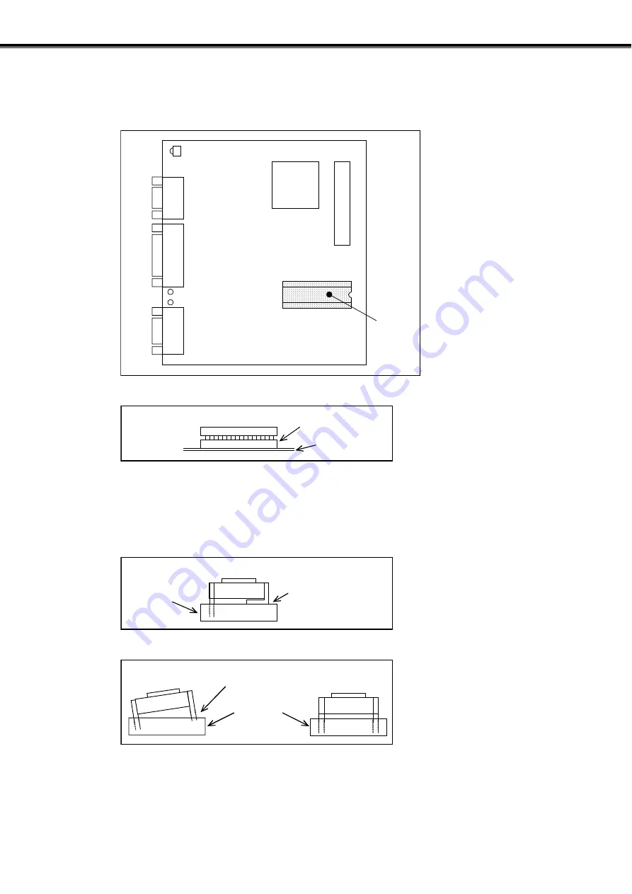
Appendix 4: How to Replace ESB Driver Unit 


3. Remove U102 on the CB board with the ROM remover.   

The B3, 23, B5, and 25 type Driver Units do not require the transfer of the ROM.   

Figure A-17: Remove the U102 ROM. 


U2 

J3

Fr

ont sid

e of 

Drver 

Unit 

U102


Figure A-18: Compensation ROM 


U102 

CB board

Socket 


4. Transfer the removed compensation ROM to the new ESB Driver Unit. 

When transferring the ROM, be careful for the orientation of the IC. Be sure to insert firmly the 
ROM in the socket. 

Figure A-19: Note 1: For inserting the ROM into the socket. 


ROM 

Be careful not to 
break the pins. 

Socket 


Figure A-20: Note 2: For inserting the ROM into the socket. 


ROM 

Right position

Inclined

Socket 


Содержание MEGATORQUE M-ESB-YSB2020AB300

Страница 1: ...excess underutilized and idle equipment along with credit for buybacks and trade ins Custom engineering so your equipment works exactly as you specify Critical and expedited services Leasing Rentals Demos In stock Ready to ship TAR certified secure asset solutions Expert team I Trust guarantee I 100 satisfaction All trademarks brand names and brands appearing herein are the property of their respe...

Страница 2: ...MEGATORQUE MOTOR SYSTEM User s Manual ESB Driver Unit System EC T Document Number C20140 01 ...

Страница 3: ...ing under this limited warranty NSK Ltd makes no other warranty express or implied and disclaims any warranties for fitness for a particular purpose or merchantability Copyright 2003 by NSK Ltd Tokyo Japan All rights reserved No part of this publication may be reproduced in any form or by any means without permission in writing from NSK Ltd NSK Ltd reserves the right to make changes to any product...

Страница 4: ...ng l Take appropriate measures not to contaminate the Driver Unit when wiring or installing 4 Storing l Store the Driver Unit in a place at where it is not exposed to rain water and harmful gas or liquid l Store the Driver Unit in a place at where it is not exposed to direct sun light Keep the ambient temperature and humidity as specified 5 Limited number of times for overwriting data l The Driver...

Страница 5: ...cation Be sure to supply a dry air The user shall take the measures against dust For a long term use check the Motor for its aging by insulation test approximately once in every half year 2 Use condition l The allowable moment load and axial load differ with Motor size Reconfirm that the using conditions are in the specified limits of the Motor l An excessive offset load or heavy load will cause p...

Страница 6: ...ue to individual Motor change 5 The Motor vibrates Positioning is inaccurate Alarm of software thermal arises frequently l Are servo parameters VG VI PG FP and NP adjusted l Do you fasten the fixing bolts of load and the Motor mounting securely Check them and fasten them tightly if necessary l Connect FG terminal of the Driver Unit to one point grounding Ground the Motor and the Driver Unit respec...

Страница 7: ... Blank Page ...

Страница 8: ...d wiring routing However your actual use conditions for wiring and installations won t be the same as our tested sample and because of this reason you have to check your machine especially on electro radiation disturbance and terminal distance voltage for the conformity to EMC Directive as a complete machine after installation of the Megatorque Motor System n List of relevant standards Item Confor...

Страница 9: ...1 or 2 as specified on IEC60664 1 The Driver Unit shall be installed into a control panel with the structure that does not allow penetration of water oil or dust IP54 u Power source The ESB Driver Unit shall be used in environmental condition of Over voltage category III as specified on IEC60664 1 u Circuit breaker Install a circuit breaker that conforms to IEC standard and UL safety standard betw...

Страница 10: ...river Unit UL508C E216221 2 1 Conditions to Meet UL Standards Be sure to meet the following as they are the supplementary conditions the qualification u Environmental conditions The Driver Unit must be used in the environmental condition of Pollution Degree1 or 2 as specified on IEC60664 1 The Driver Unit shall be installed into a control panel with the structure that does not allow penetration of...

Страница 11: ... iv Blank Page ...

Страница 12: ...Signal List 2 26 2 9 Control Input Output Interface Specifications 2 27 2 9 1 CN2 and CN5 Connectors Control I O Signal Connectors 2 27 2 9 2 Control I O Signal Specifications of B3 and 23 Type Driver Units 2 28 2 9 2 1 Selection of I O Signal Combination Type 2 28 2 9 2 2 Polarity of Input Port Nomally Open Contact and Normally Closed Contact 2 28 2 9 2 3 Pin Out CN2 B3 and 23 type Driver Units 2...

Страница 13: ... Parameter 5 4 5 2 3 Execution of Automatic Tuning Tuning Level 1 5 5 5 2 4 Trial Running Tuning Level 1 5 6 5 2 5 Minor Servo Adjustment Tuning Level 2 5 8 5 3 Manual Tuning 5 10 5 3 1 Precautions for Manual Tuning 5 10 5 3 2 Adjustment of Velocity Loop Proportional Gain VG 5 10 5 3 3 Adjustment of Velocity Loop Integration Frequency VI 5 12 5 4 Setting Filters Tuning Level 2 5 14 6 Operation 6 1...

Страница 14: ...Thermal Loading 7 33 7 1 18 8 Monitoring State of Automatic Gain Switching 7 33 7 1 18 9 Monitoring Parameter Setting 7 34 7 1 18 10 Monitoring Alarm Identification 7 35 7 1 18 11 Monitoring Contents of Channel 7 35 7 1 18 12 Monitoring Histories of Program Execution and Change on Control I O 7 36 7 1 19 Monitoring Analog Control 7 38 7 2 For More Advanced Operation 7 40 7 2 1 Absolute Position Sc...

Страница 15: ...ry 8 18 FR Feed Back Signal Resolution Factory use only 8 18 FS Low pass Filter Secondary 8 18 FW FIN Width 8 19 FZ Feedback Phase Z Configuration 8 19 GP Gain Switching Point 8 20 GT Switching Gain Timer 8 20 HA Home Return Acceleration 8 20 HD Home Return Direction 8 21 HI Home In position 8 21 HO Home Offset 8 21 HS Home Return Start 8 22 HT Hardware Travel Limit Over Alarm Type 8 22 HV Home Re...

Страница 16: ... A 8 56 ZBS Start Point of Zone B 8 56 ZBE End Point of Zone B 8 56 ZP Position damping Factory use only 8 56 ZV Velocity damping Factory use only 8 56 8 2 Parameter List 8 57 9 Maintenance 9 1 9 1 Precautions 9 1 9 2 Periodical check 9 2 9 2 1 Motor 9 2 9 2 2 Driver Unit and Cable Set 9 2 9 3 Periodical Replacement of Parts 9 3 9 3 1 Motor 9 3 9 3 2 Driver Unit 9 3 9 4 Storing 9 3 9 5 Warranty Pe...

Страница 17: ... Signals A 1 Appendix 2 How to Check Motor Condition A 7 Appendix 3 Initialization of Driver Unit A 11 Appendix 4 How to Replace ESB Driver Unit A 14 Appendix 5 Regeneration Dump Resistor A 21 Appendix 6 Wiring of RS 232C Communication Cable A 23 Appendix 7 ESBB3 Driver Unit Parameter Program List A 24 Appendix 8 ESB23 Driver Unit Parameter Program List A 25 Appendix 9 ESBB5 Driver Unit Parameter ...

Страница 18: ...B series Motors If your Motor is not one of these please refer to the attached specification document to the Motor to which the priority is given l On the upper part of each page header type codes of ESB Driver Unit to which the description on the page is applicable are indicated Confirm if the description on the page matches to your Driver Unit type referring to Table 1 1 in 1 2 Terminology B B3 ...

Страница 19: ...operating the Megatorque Motor System l Following notice is added to each clause for safety precaution to get your attention Danger Matters that may cause serious injuries if you don t follow the notes Warning Matters that may result in injuries if you don t follow the notes Caution Matters that may damage the equipment machine and or the work attached to the Motor jigs or end effector or may caus...

Страница 20: ...t to shorten it not to make it longer with another extending cable or do not to connect it to another routing with other means à If the cable is modified it may cause inaccurate positioning or noise emission Caution Never disassemble the Motor since it has been precisely assemble and tuned à If disassembled it may cause abnormalities such as deterioration in rigidity and positioning accuracy as we...

Страница 21: ... à In such a case you need to decrease velocity deceleration rate and operation duty cycle or you require an external high capacity regenerative dump resistor Refer to Appendix 5 Regeneration Dump Resistor Danger Never apply water or oil to the Driver Unit à Take appropriate measures to protect the Driver Unit from water oil slag dust and corrosive gas Figure 1 2 Warning Do not test the insulation...

Страница 22: ...angeable types l The interchangeability of a Motor and a Driver Unit won t be applicable if the Megatorque Motor Systems are made to special orders In such a case please refer to respective specification documents l Be sure to make a combination of a Motor and a Driver Unit with the same serial number when they are not interchangeable Moreover you shall use the specified Cable Set l Please be awar...

Страница 23: ...0 phase difference rated stall torque The rated torque available at zero speed rated torque The torque not to exceed the maximum Motor winding temperature s 1 Revolution per second the unit of velocity s 2 s 1 per second the unit of acceleration servo lock One typical state of servo on the Motor provides torque and remains in position servo off The state where the Driver Unit provides no current t...

Страница 24: ...solver 2 Extended I O type with analog input 5 25 type à Absolute position sensor Home Return is not necessarily every time when the power is turned on à Incremental position sensor Home Return is required every time the power is turned on à Basic type A type of Driver Unit that does not have extended I O ports Parameters set the required I O signals à Extended I O type A type of Driver Unit that ...

Страница 25: ... 1 8 B B3 3 t ty yp pe e B B5 5 t ty yp pe e 1 2 Terminology 2 23 3 t ty yp pe e 2 25 5 t ty yp pe e Blank Page ...

Страница 26: ...erial communication unit RS 232C communication terminal Personal computer etc Various types of indexing application Intermittent positioning control Analog command 10V Motor rotates accordingly to input voltage Sequencer Analog command output Servo motor controller Additional controlling axis of NC controller Velocity control mode RS 232C serial communication The master controller outputs a veloci...

Страница 27: ...art Clear position error Hardware over travel limit Pulse train command Type 7 TY7 Pulse train command 1 program channel 1 Jog Hardware over travel limit RS 232C communication Type 8 TY8 Pulse train command Eight program channels Position loop integrator frequency OFF 2 Programmable Indexer RS 232C communication 1 Input for channel selection is not available Start command RUN input uses the channe...

Страница 28: ...ire In case of a Motor equipped with brake In the dotted line The user shall provide these devices In case of using a Motor equipped with brake the user shall provide these devices u System configuration of pulse train command positioning Figure 2 2 Cable Set RS 232C communication Single phase 200 to 230 VAC or 100 to 120 VAC Main power YSB Series Megatorque Motor Seaquencer Motor controller 24 VD...

Страница 29: ...rovide these devices In case of using a Motor equipped with brake the user shall provide these devices u System configuration of analog command positioning Figure 2 4 Cable Set RS 232C communication Single phase 200 to 230 VDC or 100 to 120 VDC Main power YSB Series Megatorque Motor Seaquencer Motor controller etc 24 VDC power supply ESB Driver Unit Handy Terminal FHT11 3 2 1 5 4 8 7 6 0 9 C B A F...

Страница 30: ...d 601 Dust proof 701 High accurate rotor runout 801 High accurate absolute positioning 2 2 2 ESB Driver Unit for YSB Motor Figure 2 6 ESB Driver Unit M ESB YSB2 020 A B 3 02 Motor size code Design umber 00 Photo coupler pulse train input 01 Line receiver pulse train input 02 With terminal block for thermal sensor photo coupler pulse train input 03 With terminal block for thermal sensor line receiv...

Страница 31: ...08 8 m 015 15 m 030 30 m Design number 03 Absolute position sensor for fixed use 13 Absolute position sensor flrxible type 01 Incremental position sensor for fixed use 11 Incremental position sensor flexible type Cable set for ESB Driver 2 2 4 Handy Terminal Figure 2 8 Handy Terminal M FHT 11 Design number 2 3 Name of Parts 2 3 1 YSB Series Megatorque Motor Figure 2 9 Mounting base Motor connector...

Страница 32: ...ional Handy Terminal FHT11 4 CN2 25 pins Motor control Input Output I O signal connector 5 CN3 15 pins Resolver cable connector Connect the exclusive resolver cable 6 CN4 Connector for the Motor cable Connect the exclusive Motor cable 7 TB1 Terminal block for power input 8 Type Reference number plate 9 No Serial number plate 10 Velocity waveform monitor pins 2 Mount blacket Mount blacked may be fi...

Страница 33: ...onnector 5 CN3 15pin Resolver cable connector Connect the exclusive resolver cable 6 CN4 Motor cable connector Connect the exclusive Motor cable 7 CN5 37 pins Motor control signal Input Output I O2 connector 8 TB1 Power source terminal block 9 Type Reference number plate 10 No Serial number plate 11 Analog waveform monitor pins 12 Analog signal monitor pins 13 VR1 Adjusting pod for analog input of...

Страница 34: ...y Terminal FHT11 4 CN2 25 pins Motor control signal Input Output I O connector 5 CN3 15 pins Resolver cable connector Connect the exclusive resolver cable 6 CN4 Motor cable connector Connect the exclusive Motor cable 7 TB1 Power source terminal block 8 TB2 Thermal sensor terminal block 9 Type Reference number plate 10 No Serial number plate 11 Velocity waveform monitor pins 2 Mount bracket Mount b...

Страница 35: ...ctor 5 CN3 15 pins Resolver cable connector Connect the exclusive resolver cable 6 CN4 Motor cable connector Connect the exclusive resolver cable 7 CN5 37 pins Motor control signal Input Output connector I O5 8 TB1 Power source terminal block 9 TB2 Thermal sensor terminal block 10 Type Reference number plate 11 No Serial number plate 12 Velocity waveform monitor pin 13 Analog signal monitor pin 14...

Страница 36: ...eys superscript Connector socket DE C1 J6 Connector DE 9PF N 180 26 98 68 Alphabetic keys Special code keys SHIFT Shift key Note 1 ESC Escape key Not used CTRL Control key Not used BS Backspace key Note 2 SP Space key Note 3 ENT Enter keyNote 4 Body Liquid Crystal Display Note 1 SHIFT Press a numeric key while pressing the SHIFT key to enter a code key A superscript of the numeric keys will be ent...

Страница 37: ... VAC M ESB YSB2020C2300 200 VAC M ESB YSB2020A2500 Extended I O 100 VAC M ESB YSB2020C2500 M YSB2020JN001 200 VAC M ESB YSB3040A2300 Basic 100 VAC M ESB YSB3040C2300 200 VAC M ESB YSB3040A2500 Incremental position sensor Extended I O 100 VAC M ESB YSB3040C2500 M YSB3040JN001 2 4 2 Cable Set Table 2 5 Reference number of cable set Function Cable length Fixed use Connecting to fixed part Flexible ty...

Страница 38: ...Brake torque N m No brake 18 No brake 36 Brake voltage V No brake 24 VDC No brake 24 VDC Brake power capacity W No brake 24 No brake 26 Brake releasing time ms No brake 50 No brake 90 Brake engaging time ms No brake 30 No brake 30 Mass kg 10 14 18 22 Environmental conditions Ambient temperature 0 to 40 C Humidity 20 to 80 Indoor use only Free from dust condensation and corrosive gas Max speed s 1 ...

Страница 39: ...brake 72 No brake 145 Brake voltage V No brake 24 VDC No brake 24 VDC Brake power capacity W No brake 40 No brake 50 Brake releasing time ms No brake 140 No brake 190 Brake engaging time ms No brake 50 No brake 80 Mass kg 32 40 58 75 Environmental conditions Ambient temperature 0 to 40 C Humidity 20 to 80 Indoor use only Free from dust condensation and corrosive gas Max speed s 1 rps 3 Resolution ...

Страница 40: ...ght of payload l Moment load M F L F 3 If F is an external force then l Axial load Fa F weight of pauload l Moment load M F L A L A Caution Axial load Fa and Moment load M shall be less than the allowable axial load and moment load respectively Table 2 9 Dimension A Distance between the bearing and the rotor surface Motor reference number M YSB2020KN001 M YSB2020JN001 M YSB2020KG001 M YSB2020JG001...

Страница 41: ...y yp pe e B B5 5 t ty yp pe e 2 23 3 t ty yp pe e 2 25 5 t ty yp pe e 2 6 Dimensions 2 6 1 Motors 2 6 Dimensions 2 6 1 Motors Figure 2 16 M YSB2020KN001 and M YSB2020JN001 Figure 2 17 M YSB2020KG001 and M YSB2020JG001 ...

Страница 42: ... 17 B B3 3 t ty yp pe e B B5 5 t ty yp pe e 2 6 Dimensions 2 6 1 Motors 2 23 3 t ty yp pe e 2 25 5 t ty yp pe e Figure 2 18 M YSB3040KN001 and M YSB3040JN001 Figure 2 19 M YSB3040KG001 and M YSB3040JG001 ...

Страница 43: ... 18 B B3 3 t ty yp pe e B B5 5 t ty yp pe e 2 23 3 t ty yp pe e 2 25 5 t ty yp pe e 2 6 Dimensions 2 6 1 Motors Figure 2 20 M YSB4080KN001 and M YSB4080JN001 Figure 2 21 M YSB4080KG001 and M YSB4080JG001 ...

Страница 44: ...2 19 B B3 3 t ty yp pe e B B5 5 t ty yp pe e 2 6 Dimensions 2 6 1 Motors 2 23 3 t ty yp pe e 2 25 5 t ty yp pe e Figure 2 22 M YSB5120KN001 and YSB5120JN001 Figure 2 23 M YSB5120KG001 and M YSB5120JG001 ...

Страница 45: ... ty yp pe e 2 25 5 t ty yp pe e 2 6 Dimensions 2 6 2 ESB Driver Units 2 6 2 ESB Driver Units Figure 2 24 ESBB3 Type Can be fixed to the rear Can be fixed to the rear Heatsink Figure 2 25 ESB23 Type Can be fixed to the rear Can be fixed to the rear Heatsink ...

Страница 46: ...3 3 t ty yp pe e B B5 5 t ty yp pe e 2 6 Dimensions 2 6 2 ESB Driver Units 2 23 3 t ty yp pe e 2 25 5 t ty yp pe e Figure 2 26 ESBB5 type and ESB25 type Can be fixed to the rear Can be fixed to the rear Heatsink ...

Страница 47: ...re 2 27 Cable Set for absolute position sensor M CXXXSB03 and M CXXXSB13 Figure 2 28 Cable Set for incremental position sensor M CXXXSB01 and M CXXXSB11 Caution If you connect the cables to moving parts be sure to use the flexible type cables Caution Bending radius of the Motor Cable shall be 135 mm or over Caution Bending radius of the Resolver Cable shall be 110 mm or over ...

Страница 48: ...0 Hz single phase Motor size Maximum capacity Motor size Maximum capacity YSB2020 1 0 KVA YSB2020 0 7 KVA YSB3040 1 2 KVA YSB3040 0 9 KVA YSB4080 1 4 KVA YSB4080 1 0 KVA YSB5120 1 5 KVA YSB5120 1 0 KVA Capacity Inrush current excluded Main power Inrush current 20 A max 10 A max Power input Leakage current 3 mA rms 40Hz to 100Hz Vibration resistance 1 0 G Conforms to JIS C0911 Line noise resistance...

Страница 49: ...in 2 Prohibition of pulse train analog command input 2 Control signal Output Driver Unit ready Home Return completed Home position detected In Position Warning 3 Brake Brake control 2 Home position defined 2 Velocity threshold 2 Target proximity In target 2 Alarm Excess position error Velocity error over Software thermal sensor RS 232C error Travel limit over CPU error Resolver circuit error Over ...

Страница 50: ...stop Servo ON Selection of internal program 64 channels Start Programmable Indexer Internal program Jog operation Home Return start Select direction of rotation Interruption of Programmable Indexer Home position limit sensor Over travel limit Clear Velocity loop integration OFF Lower velocity loop gain Input command prohibited pulse train input analog command Driver Unit ready In Position à Select...

Страница 51: ...t connector Japan Aviation Electronics Industry Ltd DELC J9SAF 13L9 Mating connector type User device side Japan Aviation Electronics Industry Ltd DE 9PF N Mating connector shell type user device side Japan Aviation Electronics Industry Ltd DE C2 J6 The user shall provide these connectors They are not necessary if NSK Handy Terminal FHT 11 is used 2 8 1 1 CN1 Pin Out Figure 2 29 CN1 Pin out FG 5V ...

Страница 52: ... Electronics Industry Ltd DC 37PF N CN2 DB C15 J10 F2 Mating connector shell type User device side CN5 Japan Aviation Electronics Industry Ltd DC C8 J13 F1 1 These connectors will be provided with the Driver Unit à B3 and 23 type Driver Units do not have connector CN5 l The followings are wiring precautions for the connectors CN2 and CN5 1 Use shielded cable for wiring of the connectors CN2 and CN...

Страница 53: ...ystem the shipping set is Type 1 l The parameter TY sets a combination type of I O signal function l The parameter TY requires entry of the password before its input l Input of the parameter TY clears all polarity of the input ports to the normally closed contact A contact 2 Output Port l A function among Brake Velocity threshold Target proximity In target and Warning shall be set to the output OU...

Страница 54: ...Z SGND DRDY IPOS DC24 EMST HLS CLR OTP CWP CCWP CHA CHB CHZ OUT1 DRDY COM Type 4 TY4 Pulse train input Home Return start Clear Over travel SVON RUN DIR OTM CWP CCWP CHA CHB CHZ SGND DRDY IPOS DC24 EMST HLS JOG OTP CWP CCWP CHA CHB CHZ OUT1 DRDY COM Type 7 TY7 Pulse train input JOG Over travel 13 12 11 10 9 8 7 6 5 4 3 2 1 25 24 23 22 21 20 19 18 17 16 15 14 25 24 23 22 21 20 19 18 17 16 15 14 13 1...

Страница 55: ...program channel selection 0 10 PRG2 Input Internal program channel selection 2 11 HLS Input Home position limit sensor 12 EMST Input Emergency stop 13 DC24 Input 24 VDC external power supply 14 IPOS Output In position positioning completed 15 DRDY Output Driver Unit ready 16 SGND Signal ground 17 CHZ 2 Output Position feedback signal øZ Digital position signal MSB 2 18 CHB Output Position feedback...

Страница 56: ...PRG2 Input Internal program channel selection 2 11 HLS Input Home position limit sensor 12 EMST Input Emergency stop 13 DC24 Input 24 VDC external power supply 14 IPOS Output In position positioning completed 15 DRDY Output Driver Unit ready 16 SGND Signal ground 17 CHZ 2 Output Position feedback signal øZ Digital position signal MSB 2 18 CHB Output Position feedback signal øB 19 CHA Output Positi...

Страница 57: ... PRG2 Input Internal program channel selection 2 11 HLS Input Home position limit sensor 12 EMST Input Emergency stop 13 DC24 Input 24 VDC external power supply 14 IPOS Output In position positioning completed 15 DRDY Output Driver Unit ready 16 SGND Signal ground 17 CHZ 2 Output Position feedback signal øZ Digital position signal MSB 2 18 CHB Output Position feedback signal øB 19 CHA Output Posit...

Страница 58: ...rection clockwise 10 CLR Input Clear input 11 HLS Input Home position limit sensor 12 EMST Input Emergency stop 13 DC24 Input 24 VDC external power supply 14 IPOS Output In position positioning completed 15 DRDY Output Driver Unit ready 16 SGND Signal ground 17 CHZ 2 Output Position feedback signal øZ Digital position signal MSB 2 18 CHB Output Position feedback signal øB 19 CHA Output Position fe...

Страница 59: ...limit switch direction clockwise 10 JOG Input Jog 11 HLS Input Home position limit sensor 12 EMST Input Emergency stop 13 DC24 Input 24 VDC external power supply 14 IPOS Output In position positioning completed 15 DRDY Output Driver Unit ready 16 SGND Signal ground 17 CHZ 2 Output Position feedback signal øZ Digital position signal MSB 2 18 CHB Output Position feedback signal øB 19 CHA Output Posi...

Страница 60: ...RDY Output Driver Unit ready 16 SGND Signal ground 17 CHZ 2 Output Position feedback signal øZ Digital position signal MSB 2 18 CHB Output Position feedback signal øB 19 CHA Output Position feedback signal øA 20 CCWP Input Counter clockwise pulse train CCW 21 CWP Input Clockwise pulse train CW 22 PRG1 Input Internal program channel selection 1 23 IOFF 3 CLCN 4 Input When parameter BF0 is specified...

Страница 61: ... inputting the parameter AB l The signals whose polarity can be changed are limited to EMST HLS OTP and OTM For B3 and 23 type Driver Units polarity change of OTP and OTM signals are only available in 3 4 and 7 types l Refer to 3 4 3 2 Setting of Input Port Polarity for setting polarity 2 9 3 2 Pin Out CN2 and CN5 B5 and 25 type Driver Units Figure 2 31 SVON IOFF CLCN HOS OTM CWP CCWP CHA CHB CHZ ...

Страница 62: ...ergency stop 13 DC24 Input 24 VDC external power supply 14 IPOS Output In position positioning completed 15 DRDY Output Driver Unit ready 16 SGND Signal ground 17 CHZ 1 Output Position feedback signal øZ Digital position signal MSB 1 18 CHB Output Position feedback signal øB 19 CHA Output Position feedback signal øA 20 CCWP Input Counter clockwise pulse train CCW 21 CWP Input Clockwise pulse train...

Страница 63: ...rogram channel selection 5 17 RUN Input RUN move 18 STP Input Stop 19 DC24 Input 24 VDC external power supply 20 SPD Output Velocity threshold 21 HOME 2 Output Home Return completed Home Position detected 2 22 HCMP Output Home position defined 23 Never connect 24 Never connect 25 Never connect 26 MON Output Analog monitor output 27 MON Output Analog monitor output 28 Never connect 29 Never connect...

Страница 64: ... voltage 24 VDC 10 Input impedance 3 3 kW Maximum current 10 mA or less per input Figure 2 32 3 3 kW 680 W Driver Unit side 24 VDC input You may reverse the polarity of the external power supply and connect as minus common 2 9 4 2 Pulse Train Input Applicable inputs CCWP CCWP CWP and CWP 1 Photo coupler specification Driver Unit reference number M ESB YSB 00 and M ESB YSB 02 Table 2 25 Item Specif...

Страница 65: ...s µA9637AC Recommended line receiver Japan Texas Instruments µA9638C or AM26LS31 equivalent Figure 2 34 Driver Unit side Input Input 1 k 1 k 2 4 k 2 4 k 2 4 k 100 p 2 9 4 3 General Output Applicable output BRK IPOS OVER HOME HCMP SPD NEARA and NEARB 1 Photo coupler specification Driver Unit reference number M ESB YSB 00 and M ESB YSB 01 Table 2 27 General output photo coupler specification Item Sp...

Страница 66: ...MOS FET specification Driver Unit reference number M ESB YSB 02 and M ESB YSB 03 Table 2 28 General output Photo MOS FET Item Specification Max load capacity 24 VDC 50mA Max saturated voltage 2 V or less Max on resistance 25 W Driver Unit side Output 1 Output 2 COM Figure 2 36 General output Photo MOS FET Connect a corresponding output signal of connectors CN2 and CN5 to output COMMON ...

Страница 67: ...ck Signal Output Applicable output CHA CHB CHZ CHA CHB and CHZ Table 2 30 Specifications of position feedback output signal Item Specification Output format Line driver CHA CHB CHA and CHB Line driver or open collector CHZ and CHZ May be selected by Jumper pin P1 Refer to 2 14 1 JP1 Line driver Texas Instruments SN75ALS192 Recommended line receiver Texas Instruments SN75ALS192 or AM26LS32 equivale...

Страница 68: ...AIN and AIN Table 2 31 Specifications of analog command input Item Specification Max input voltage 10 VDC Input impedance 20 kW Maxi input current 0 5 mA Figure 2 39 Driver Unit side 20 kΩ AIN AIN 2 9 4 7 Analog Control Monitor Applicable output MON and MON Table 2 32 Analog control monitor Item Specification Output Op amp Max output voltage 10 V 10 Saturated voltage 4 mA or less Figure 2 40 MON M...

Страница 69: ... 5 4 3 2 1 15 14 13 12 11 10 9 15 14 13 12 11 10 9 INC C FG INC A INC B COMMON 8 7 6 5 4 3 2 1 23 and 25 type Driver Units INC C ABS C FG INC A INC B ABS A ABS B COMMON B3 and B5 type Driver Units 2 10 2 Signal List Table 2 34 Signal list Pin Signal name Function 8 INC A Incremental resolve signal øA 7 INC B Incremental resolver signal øB 15 INC C Incremental resolver signal øC 6 ABS A Absolute re...

Страница 70: ...AMP K K 172774 1 Provided with the Driver Unit 2 11 1 Pin out Figure 2 42 Pin out 7 6 4 3 2 1 5 C C E A A B B 2 11 2 Signal List Table 2 36 Signal list Pin Signal Name Function 1 A Motor winding øA 2 A Motor winding øA 3 B Motor winding øB 4 B Motor winding øB 5 C Motor winding øC 6 C Motor winding øA 7 E Motor winding ground Danger Do not connect or disconnect the connector when the power of Driv...

Страница 71: ...rminal Code Function CONT Control power input MAIN Main power input GND Frame ground 2 12 2 Wiring Diagram Figure 2 36 Wiring diagram Control power Single phase 100 VAC or Single phase 200 VAC Control power Single phase 100 VAC Main power Single phase 100 VAC Main power Single phase 200 VAC MAIN AC 200 230 V CTRL AC 100 230 V TB1 L N In case of 100 VAC main power In case of 200 VAC main power L N ...

Страница 72: ...t ty yp pe e 2 13 TB2 Terminal Block for Thermal 2 13 1 Terminal Code and Function Table2 38 TB2 terminal code and function Terminal code Function S1 Terminal for thermal sensor output S2 Terminal for thermal sensor output 2 13 2 Wiring Diagram Figure 2 44 TB2 wiring diagram Motor cable thermal sensor output terminal TB2 S1 S2 User device alarm input ...

Страница 73: ...put Mode Selection of øZ Figure 2 45 Position of jumper pins OC LD JP1 CN3 CN2 CN1 7 segments LED Front panel side Table 2 39 Pin setting Output mode of øZ LD short shipping set Line driver OC short Open collector Caution Remove the panel of the Driver Unit referring to Appendix 4 How to Replace ESB Driver Unit when changing the jumper setting ...

Страница 74: ...the respective nameplates conform to each other The figure below shows the coding and numbering system of the reference number of Motor and Driver Unit Figure 3 1 Indication on the nameplate of Motor SERIAL NO YSB2 02001 REF NO M YSB 2 020 KN001 Maximum torque Motor size code Motor series code Serial number Position sensor code Figure 3 2 Indication on the nameplate of Driver Unit No Type 2 11020 ...

Страница 75: ...Danger The brake may not function if iron made member exists near the brake Please provide 15 mm or more clearance around the Motor 3 2 1 2 Loading Attachment Work to Motor Warning Use all of the tapped holes on the rotor of Motor to fix an attachment Fasten the bolts securely so that there will be no play between the rotor and the attachment load 3 2 1 3 Checking Load Inertia l The load inertia i...

Страница 76: ...sult in failure of electric circuits of the Driver Unit because of the contaminant through the openings of the Driver Unit IP code is specified in IEC standard and classifies the protection level of enclosures from solid contaminant and water Protection against external solid contaminant 5 Dust proof Protection against water 4 Must not be affected by water splash in any direction Caution When inst...

Страница 77: ...r or longer You need to purchase separately the cable with specified length Ask you local NSK representative for more details l The cable length is available in 2 4 8 15 and 30 m Caution Do not place the power lines AC main power and Motor cable and the signal lines in close proximity Do not tie wrap them and not to put in the same duct Figure 3 4 YSB type Megatorque Motor To CN3 To CN4 ...

Страница 78: ...ate the wiring s of the primary and the secondary noise filters and take different routing l The Driver Unit and the noise filter shall be close to each other l Be sure to install the surge killer circuit to the coils of magnetic switch relay and solenoid l An inrush current flows when the power is turned on because the capacitive load is connected to the main power supply circuit For this reason ...

Страница 79: ...ormally closed à Capacity Maximum 250 VAC 3 5 A Minimum 6 V 0 15 A à Model T100R1U1N Matsushita Electric Industrial Co Ltd Set temperature 100 à Conforms to VDE à The sensor is an auto regression type It returns to normal state when the temperature becomes 15 C lower than set temperature Turn on the main power 30 minutes after the shutdown circuit activated 3 3 4 Ground Connection Caution Connect ...

Страница 80: ... ELB1 Short circuit breaker CB1 Non fuse breaker NF1 Noise filter MC1 Magnetic switch RY1 Relay SW1 Main power switch ON SW2 Main power switch OFF NF 15 2 SW1 SW2 MC1 MC1 RY1 CB1 Thermal sensor normally closed Caution We recommend the following noise filter for an measures against EMC Directive à PN2070 10 06 Schaffner equivalent Use a breaker compatible with the European Safety Directives Caution...

Страница 81: ... Short circuit breaker CB1 Non fuse breaker NF1 Noise filter MC1 Magnetic switch RY1 Relay SW1 Main power switch ON SW2 Main power switch OFF NF 15 2 SW1 SW2 MC1 MC1 RY1 CB1 Thermal sensor Normally closed TB2 S1 S2 Caution We recommend the following noise filter for an measures against EMC Directive à PN2070 10 06 Schaffner equivalent Use a breaker compatible with the European Safety Directives Ca...

Страница 82: ...osition limit switch Start positioning Internal program channel selection 0 Internal program channel selection 1 Internal program channel selection 2 Internal program channel selection 3 Driver Unit ready Positioning completed Brake Veocity threshold Proximity In target Over 13 DC24 25 SVON 12 EMST 11 HLS 24 RUN 9 PRG0 22 PRG1 10 PRG2 23 PRG3 15 DRDY 2 DRDY 14 IPOS 3 OUT1 1 1 COM FG User s control...

Страница 83: ... threshold Proximity Intarget Over 13 DC24 25 SVON 12 EMST 11 HLS 24 RUN 9 JOG 22 DIR 10 PRG2 23 PRG3 15 DRDY 2 DRDY 14 IPOS 3 OUT1 1 1 COM FG User s controller ESB Driver Unit CN2 24 VDC DC24V l Home Return à For an example write HS command to channel CH0 and then à Select the CH0 to start the Home Return RUN input ON after turning on the power and complete the Home Return l Pulse train command o...

Страница 84: ...sitioning completed Brake Velocity threshold Proximity In target Over 13 DC24 25 SVON 12 EMST 11 HLS 24 RUN 9 OTP 22 OTM 10 PRG2 23 PRG3 15 DRDY 2 DRDY 14 IPOS 3 OUT1 1 1 COM FG User s controller ESB Driver Unit CN2 24 VDC 24 VDC l Home Return à For an example write HS command to channel CH0 and then à Select the CH0 to start the Home Return RUN input ON after turning on the power and complete the...

Страница 85: ...ning Over travel limit direction Over travel limit switch direction Clear Start Home Return User s controller ESB Driver Unit Position feedback signal øZ digital position signal MSB Position feedback signal øB Position feedback signal øA 5 VDC CW pulse train CCW pulse train 24 VDC Signal ground 13 DC24 25 SVON 12 EMST 11 HLS 24 RUN 9 OTP 22 OTM 10 CLR 23 HOS 8 CWP 21 CWP 7 CCWP 20 CCWP 15 DRDY 2 D...

Страница 86: ...ntroller ESB Driver Unit Position feedback signal øZ Digital position signal MSB Position feedback signal øB Position feedback signal øA 5 VDC CW pulse train CCW pulse train 24VDC Signal ground 13 DC24 25 SVON 12 EMST 11 HLS 24 RUN 9 OTP 22 OTM 10 JOG 23 DIR 8 CWP 21 CWP 7 CCWP 20 CCWP 15 DRDY 2 DRDY 14 IPOS 3 OUT1 1 1 COM 6 CHA 19 CHA 5 CHB 18 CHB 17 CHZ 4 CHZ 16 SGND CN2 FG l Home Return à For a...

Страница 87: ...UN 9 PRG0 22 PRG1 10 PRG2 23 IOFF CLCN 1 15 DRDY 2 DRDY 14 IPOS 3 OUT1 2 1 COM FG User s controller ESB Driver Unit CN2 24 VDC 24 VDC l Home Return à For an example write HS command to channel CH0 and then à Select the CH0 to start the Home Return RUN input ON after turning on the power and complete the Home Return l Pulse train command positioning à When you control the System by the pulse train ...

Страница 88: ...Circuit breasker Magnetic switch Noise filter User sahll provide devices in the dotted line Handy Terminal FHT11 3 2 1 5 4 8 7 6 0 9 C B A F E D I H G L K J O N M R Q P U T S X W V Z Y CTRL ESC S HIFT ENT S P BS NSK HANDY TERMINAL YSB Megatorque Motor Power supply for electromagnetic brake 24 VDC GND RL1 Serge absorber CTRL CN4 MOTOR MAIN FGND TB CN3 SENSOR 13 DC24 25 SVON 12 EMST 23 IOFF CLCN 1 1...

Страница 89: ...ler ESB Driver Unit Position feedback signal øZ digital position signal MSB Position feedback signal øB Position feedback signal øA 5 VDC Driver Unit ready Positioning completed Brake Brake control CW pulse train CCW pulse train 24 VDC Porality of the power supply may be reversed to minus common Signal ground 24 VDC F G Warning Home Retrun completed Home postion detected Home postion defined Detec...

Страница 90: ...gnal øB Velocity Torque control mode Analog command input 10 VDC Position feedback signal øA Driver Unit ready Positioning completed Brake Brake control 24 VDC Signal ground 24 VDC FG 13 DC24 25 SVON 12 EMST 9 OTP 22 OTM 10 CLR 24 IOFF CLCN 1 15 DRDY 2 DRDY 14 IPOS 3 BRK BRKC 1 1 COM 6 CHA 19 CHA 5 CHB 18 CHB 17 CHZ 4 CHZ 16 SGND 8 AIN 7 AIN 19 DC24 36 INH 2 OVER 20 SPD 3 NEARA 4 NEARB 1 COM CN5 C...

Страница 91: ...on OFF Brake off Clear CW pulse train CCW pulse train 5 VDC ø3 200 VAC or ø1 200 VAC 100 VAC R S T Isolation transformer Circuit breaker Electromagntic switch Noise filter etc The user shall provide these circuit Handy Terminal FHT11 3 2 1 5 4 8 7 6 0 9 C B A F E D I H G L K J O N M R Q P U T S X W V Z Y CTRL E SC SHIFT ENT SP B S NSK HANDY TERMINAL Megatorque Motor Brake power supply 24 VDC GND R...

Страница 92: ...n 1 Turn on the power and make sure that the LED on the front panel of the Driver Unit is indicating normal state Figure 3 17 In a state of alarm P o w e r L E D It is o n w h e n th e p o w e r is o n 7 s e g m e n ts L E D Id e n tifie s a typ e o f a la rm l It in d ic a te s a typ e o f a la rm in 2 d ig its T h e n u m b e rs w ill b e s h o w n in tim e s h a rin g l If tw o o r m o re a la ...

Страница 93: ... password for inputting the parameter TY l Input of the TY parameter will clear polarity of all input ports to the normally open contact However if you set the same parameter data to the TY parameter as before the Driver Unit maintains the current polarity setting Data indication of polarity AB is bit map format and its order and relation between the TY and I O combination type are listed on Table...

Страница 94: ...input will be the CLCN Brake off input when the brake sequence function BF1 is activated under the I O type 8 TY8 2 Output port l A function among Brake BRK Brake control BRKC Velocity threshold SPD Target proximity In target NEARA and Warning OVER shall be set to the OUT1 pin 3 output of CN2 connector l The shipping set is Brake BRK output l The parameter OM sets the function of output port for t...

Страница 95: ...all the CN2 input ports is the normally open contact l Parameter AB sets the polarity of input ports l You need the password before inputting the parameter AB l The signals that can select the polarity are limited to EMST HLS OTP and OTM OTP and OTM inputs are only available for the types of 3 4 and 7 in case of B3 and 23 Driver Units Table 3 8 Data order of parameter AB Data digit from left 1 2 3...

Страница 96: ...ol I O Signal Ports 3 Input the password The display indicates the acknowledgement ABX0X0XX00 NSK ON NSK ON _ S N SP K ENT N O 4 Input 1 to the second bit that correspondin and then input x for other ports NSK ON NSK ON ABX1XXXXXX _ X B A X X 1 X X X ENT X l Polarity of EMST Emergency stop port is thus set to the normally closed contact ...

Страница 97: ...m Servo lock Operating Motor Master controller User s controller Driver Unit side Initialization DRDY closed DRDY open SVON NG OK NG OK Operation command DRDY check Action for alarm Check conditio Figure 3 21 Timing for Power and Servo ON Confirmed 2 sce approximately See note ON OFF 30ms min ON OFF ON OFF Control power Main power DRDY output SVON input Operation command Home Return etc See note I...

Страница 98: ...communication u Appearance and function of each part Figure 4 1 Cable 86 3 2 1 5 4 8 7 6 0 9 C B A F E D I H G L K J O N M R Q P U T S X W V Z Y CTRL ESC SHIFT ENT SP BS HANDY TERMINAL NSK NSK JAE DE C1 J6 Cable length 3000 Unit mm 38 19 Numeric keys Code keys superscript Connector socket DE C1 J6 Connector DE 9P N 180 26 98 68 Alphabetic keys Special code keys SHIFT Shift key Note 1 ESC Escape ke...

Страница 99: ...ter code data ENT to set the parameter No space is required between the parameter code and the data 4 1 2 Setting With the Password 1 Connect the Handy Terminal to the CN1 connector of the ESB Driver Unit and turn on the power 2 Confirm that the colon is on the screen Press the ENT key once if the colon is not on the screen _ ENT 3 Enter the Password NSK ON NSK ON _ K N S SP N ENT O The acknowledg...

Страница 100: ...y once if the colon is not on the screen _ ENT 3 As an example let s read out the setting of parameter JV for Jog velocity The parameter JV belongs to a group of TS7 according to the description of TS command shown in 8 Glossary of Command and Parameter Enter as shown below to the Handy Terminal TS7 MV1 00 ENT S 7 T The screen will show firstly the setting of the parameter MV for the velocity of t...

Страница 101: ...not on the screen _ ENT 3 As an example let s read out current setting of the parameter JV for the Jog velocity Add before the parameter code that is to be read out then enter to the Handy Terminal as follow for the example JV JV0 10 _ ENT J V The screen indicates the setting of the parameter JV and the colon appears on the screen as the indication that the Driver Unit is ready for an entry of new...

Страница 102: ...rs will be done in this stage Automatic setting of PG VG VIMA and MA parameters l Initialize the servo parameters 5 2 3 Execution of Automatic Tuning End of trial running 5 2 4 Trial Running Power on Preparation 5 2 2 Initialization of Servo Parameter Caution Make sure that the LED shows normal state Turn on the power of the Driver Unit and confirm that the screen of Handy Terminal displays a mess...

Страница 103: ...t à Connection of the Handy Terminal à Connection of AC power source à Wiring of the signals of Servo ON SVON and Emergency stop EMST Connector CN2 5 2 1 Precautions Danger Be sure to wire an input of the Emergency stop EMST and an input of the Over Travel limit switch OTP OTM if the off limits zone is set so that the Motor can stop immediately in case of emergency Danger The Motor will rotate for...

Страница 104: ...etup CN1 TB CN4 Control power CONT CN3 Main power MAIN FGND 24DC 13 SVON 25 CN2 EMST 12 OTP 9 OTM 22 Mounting base Work or attachment Load inertia AC power Handy Terminal 24 VDC external power supply Cable set Motor Sensors for over travel limit 3 2 1 5 4 8 7 6 0 9 C B A F E D I H G L K J O N M R Q P U T S X W V Z Y CTR L ESC SHIFT ENT SP BS NSK HANDY TERMINAL AC power ...

Страница 105: ...d to initialize the parameters The screen displays the acknowledgment INITIALIZE and the System starts the parameter initialization It requires few seconds to complete The colon will appear on the screen when the initialization completes SI INITIALIZE _ I ENT S Caution Be careful that the System won t accept the SI command if the SVON signal remains ON The message SI INHIBITED will appear on the s...

Страница 106: ...the normal state 3 Enter the command for execution of the automatic tuning If the message on the screen is not the same as shown below follow the procedures in 1 and 2 AT AT ready OK _ T ENT A 4 Confirm the message and then input OK The Motor rotates 10 to 20 after the input and then an estimation of the inertia starts The screen displays a dot every time the Motor rotates during the estimation of...

Страница 107: ...e 3 Confirm that the Emergency stop EMST and the Over travel limit OTP and OTM of the CN2 connector are not inputted 4 The Motor velocity is initialized to 1 s 1 Decrease the velocity MV to 0 1 s 1 for the trial running MV0 1 _ V 0 M 1 ENT 5 Display a menu screen of the demonstration program SP AJ IN100 IS0 0 FW1 0 ID9000 OK _ P S J ENT A It indicates the conditions for completion of positioning a...

Страница 108: ...ange the rotation angel to 30 Type as ID3000 IN10 IS0 5 FW1 0 ID3000 OK _ D 3 I 0 0 ENT 0 8 Input MS command to stop the Motor after the result of trial running is confirmed MS _ S ENT M 9 Display the demonstration program screen to quit the trial running IN10 IS0 5 FW1 0 ID3000 OK _ P S J ENT A When quitting the demonstration without performing the cyclic motion press the ENT key following the pr...

Страница 109: ... parameter The screen displays the message as shown below and you can change SG setting up and down using the key and the key Actually the SG parameter differs with the load inertia and the rotation angel ENT 444 333 STEP1 _SG10 G S J ENT A 1 5 2 3 4 l Explanation of the message screen 1 Key function and SHIFT Pressing the key one time increases 1 resolution of SG Pressing the keys one time decrea...

Страница 110: ...ndex decreases 3 Keep pressing the key and eventually the Motor will start hunting and then stop reciprocating motion ENT 233 123 STEP1 _SG18 Pressing SHIFT 4 Press the key several times to lower the SG setting until the Motor stops hunting and starts reciprocating motion ENT 253 145 STEP1 _SG16 5 Decrease the SG to 80 of SG value at where the Motor stopped hunting and the Motor shows stable motio...

Страница 111: ...ter The screen displays the message as shown below and you can change VG setting up and down using the key and the key Actually the VG parameter differs with a load inertia and rotation angel ENT 444 333 STEP1 _VG1 G V J ENT A 1 5 2 3 4 l Explanation of the message screen 1 Key function and SHIFT Pressing the key one time increases 1 resolution of the VG Pressing the key one time decreases 1 resol...

Страница 112: ...IFT 4 Press the key several times to lower the VG setting until the Motor stops hunting and starts reciprocating motion ENT 253 145 STEP0 1 _VG4 5 Obtain a SG setting that is 80 of the SG at where the hunting stopped If the hunting stopped at VG4 calculate as 4 0 8 3 2 This data shall be set to the parameter VG 6 Press the SP key once to make the changing resolution of VG for one press of the or k...

Страница 113: ... the key one time increases 1 resolution of the VI Pressing the key one time decreases 1 resolution of the VI ENT Press the key to store the VI setting 2 This part indicates the current setting of VI 3 This part indicates the changing resolution of VI data when the or the key is pressed VI changing resolution 4 Response index number Small number denotes better response to the command 5 Positioning...

Страница 114: ... Obtain a VI data that is 80 of VI at where the hunting stopped If the hunting stopped at VI4 calculate as 4 0 8 3 2 This data shall be set to VI 5 Press the SP key once to make the changing resolution of VI for one press of the or key to 0 1 ENT 263 156 STEP0 1 _VI4 SP 6 Press the key several times until the VI data changes to the new setting ENT 263 156 STEP0 1 _VI3 2 7 Press the ENT key to comp...

Страница 115: ...tart the adjusting program of the parameter FP The screen displays the message as shown below and you can change the FP setting up and down using the and the keys Actually the FP parameter differs with a load inertia and rotation angel ENT 444 333 STEP10 _FP500 P F J ENT A 1 5 2 3 4 l Explanation of the message screen 1 Key function and SHIFT Pressing the key one time increases 10 units of FP reso...

Страница 116: ...ing ENT 233 123 STEP1 _FP120 SHIFT 4 Press the ENT to complete the setting 233 123 STEP1 FP120 _ ENT Reference When terminate the low pass filter FP0 _ ENT P 0 F Reference Adjusting notch filter l When setting the notch filters NP and NS you need to measure the resonant frequency by checking voltage between the analog velocity monitor pins VELOCITY GND terminals on the front panel of Driver by mea...

Страница 117: ... 5 16 B B3 3 t ty yp pe e B B5 5 t ty yp pe e 5 4 Setting Filters Tuning Level 2 2 23 3 t ty yp pe e 2 25 5 t ty yp pe e Blank Page ...

Страница 118: ...Table 6 1 No Items to be checked Points to be checked 1 Connection of main power and Input Output signal cables Check if the wiring is properly done Check if the screws of the terminal block are securely fastened Check if the connectors are properly connected and secured 2 Connecting cables Check if the cable sets Motor cable and resolver cable are properly connected and locked to the connectors 3...

Страница 119: ...itioning Operation See 6 2 5 RS 232C Communication Positioning Operation See 6 2 4 Jog See 6 3 Veleocity Control Mode Operation Velocity control mode See 6 4 Torque Control Mode Operation Torque control mode RS 232C communication command operation Analog command operation See 6 3 1 RS 232C Communication Command See 6 3 2 Analog Command Operation RS 232C communication command operation Analog comma...

Страница 120: ...ols the position scale l For the B3 and B5 type Driver Units execute the Home Return only when you need to change the home position because they are for the Motors with the absolute position sensor l The positioning and setting of software over travel limits depend on these position scales l There are two ways of setting the home position One is to set the current position as the home position wor...

Страница 121: ...home position by the AZ command 1 Set the Motor servo free MO _ O ENT M 2 Rotate the Motor to the position to be the user home position and hold the position 3 Input the password The acknowledgement appears on the display MO NSK ON NSK ON _ K N S SP N ENT O 4 Input of the AZ command sets the user home position and resets AO value offset from the zero position NSK ON AZ AO1234 _ Z ENT A The user ho...

Страница 122: ...S CR HA CR stands for carriadge return code 0DH 10 ms min HO HZ HV Setting of FW RS 232C communication command Closed Open Closed Open Closed Open When HO 0 2 3 4 l Make the Motor servo on SVON input is ON l The Home Return starts when the HOS input turns ON 1 Table 6 2 Control Input Output related to Home Return operation Signal Function I O Chapter to be referred SVON Servo ON Input 7 1 1 Servo ...

Страница 123: ...for the offset value from the 0 point of the position sensor then completes Home Return operation l The Home Return can be also executed with the following ways à Select t a channel where the HS command is set and then input the RUN command à Execute the HS command through the RS 232C communication l The Home Return sequence differs by the starting point of Home Return as shown in Figure 6 4 Figur...

Страница 124: ... Zero velocity creeping speed when the home limit sensor HLS is ON l Home position is set on the point at where the home limit sensor is off Figure 6 5 Mode1 OS1 Starting point of Home Return Point at the Home Return completed HLS input ON Home position proximity CW direction CCW direction CCW direction CW direction 2 Mode 3 OS3 l Home Return velocity changes to Near Zero velocity when the home li...

Страница 125: ...sition Figure 6 7 Mode 4 OS4 øZ HO Starting point of Home Return Point at Home Return completed HLS input ON Home position proximity CW direction CCW direction CCW direction CW direction 4 Mode 5 OS5 l The Motor slows down and reverses its motion when the home limit sensor is on Then it reverses its motion with Near Zero velocity after getting out the home position proximity range and searches the...

Страница 126: ... to the width of a tooth l The following are the procedures for adjusting the home limit sensor u Adjusting procedure Adjusting position of the home limit sensor 1 Temporally set the limit sensor The position shall be slightly preceding a point to be the home position 2 Check wiring of the home limit sensor Check if the ESB Driver Unit is reading the HLS input normally with execution of the IO com...

Страница 127: ...NT key will turn the Motor sevo off TR8006 OK MO _ ENT The Motor can be turned easily Rotate the Motor to the desired position However do not turn it more than one revolution 5 Input the password TR8006 OK MO NSK ON_ K N S SP N O 6 Press the ENT key MO NSK ON NSK ON _ ENT 7 The position sensor will automatically detect and store the Home position offset value HO by HO ST command MO NSK ON NSK ON H...

Страница 128: ...command is to make the Servo on NSK ON HO ST HO1234 SV_ V S 10 Entering the ENT key turns the Motor servo on _ indicates the acceptance of the command HO ST HO1234 SV _ ENT 11 The HS command is for execution of Home Return HO ST HO1234 SV HS_ S H 12 Entering the ENT key starts the Home Return HO1234 SV HS _ ENT Check if the Motor stops at the point as desired ...

Страница 129: ...H 0 C The prompt changes to and the Driver Unit waits for input of the data If data have been programmed in the CH0 at this moment it will be indicated on the screen 2 Input the command for Home Return CH0 HS _ S ENT H 3 Input of the ENT key following the prompt completes programming to the CH0 CH0 HS _ ENT l Following instructions show a trial running to check Motor motion when Home Return accele...

Страница 130: ...put of RUN command will not be accepted l Execution of the SP command may start the built in program The same function as RUN input ON Inputting SPm ENT m program channel number will start the program of Channel m Figure 6 9 Command timing of Programmable Indexer In case of BF0 brake sequence invalid CW or CCW velocity RUN input invalid MA or CA Servo ON SVON input Channel selection PRG0 PRG5 inpu...

Страница 131: ...Positioning completed IPOS output FW 0 IPOS output FW 0 Position loop integration Brake action Valid Invalid Motor motion WU Brake off timer WC Brake on timer IS In position Position error IN stability counter FW IPOS signal outputting time ON OFF Closed Open Brake power on Brake power off Closed Open Integration valid Integration invalid Brake off Brake on Open Closed 6 5 4 3 2 1 Table 6 4 Contro...

Страница 132: ...4 ü ü ü ü 5 OFF OFF OFF ON OFF ON 5 ü ü 6 OFF OFF OFF ON ON OFF 6 ü ü 7 OFF OFF OFF ON ON ON 7 ü ü 8 OFF OFF ON OFF OFF OFF 8 ü ü ü 9 OFF OFF ON OFF OFF ON 9 ü 10 OFF OFF ON OFF ON OFF 10 ü 11 OFF OFF ON OFF ON ON 11 ü 12 OFF OFF ON ON OFF OFF 12 ü ü ü 13 OFF OFF ON ON OFF ON 13 ü 14 OFF OFF ON ON ON OFF 14 ü 15 OFF OFF ON ON ON ON 15 ü 16 OFF ON OFF OFF OFF OFF Available number of channels 16 4 4...

Страница 133: ...63 channels of program area for the B5 and 25 type Driver Units Figure 6 11 Program area B3 and 23 Driver Units B 5 and 25 Driver Units Channel 0 CH0 Channel 0 CH0 Channel 1 CH1 Channel 1 CH1 Channel 15 CH15 Channel 63 CH63 1 Parameters for command and condition setting u Home Return Command HS Condition parameter None l Programs the Home Return l Command format HS seq seq Sequence code l The Moto...

Страница 134: ...3 seq Incremental position command in the unit of degree The Motor rotates the distance of d1 unit 0 01 from the current position IR d1 d2 d3 seq Incremental position command in the unit of pulse The Motor rotates the distance of d1 unit pulse from the current position 1 Option code d2 n n 99 Divides the d1 by the data n and makes the quotient a step of positioning distance The default does not di...

Страница 135: ...CH0 IR1000 CH1 TI10 CH2 IR 1000 Figure 6 13 IR1000 TI10 IR 1000 CH0 PRG0 5 RUN input Programmed positioning IPOS output FW 0 CH1 CH2 0 1 sec u Jump Command JP Condition setting None l This command sets unconditional jump l Command format JP m m Channel number to jump Default 0 l The program sequence jumps to a specified channel and executes its program Program example CH0 IR1000 CH1 IR2000 CH2 JP0...

Страница 136: ...output Executing condition for the next channel Asterisk Available Continue to execute after the positioning Ampersand Available Stops after the positioning and waits for RUN input Program example CH0 IR500 CH1 IR1000 Figure 6 15 IR500 IR1000 CH0 PRG0 5 RUN input Programmed positioning IPOS output FW 0 CH1 0 u Changing sequence code Condition parameter OE l OE seq can change a sequence code curren...

Страница 137: ...ut The prompt is The last program is valid when the change has been made Readout of channel program TC Input TCm ENT M channel number and press the SP key to scroll for reading out program set in the channel number m Input TC AL ENT and press the SP key to scroll all channel for readout of programs Delete program CC Input CCm ENT m program channel number to erase a program in channel number m Dele...

Страница 138: ...iver Unit waits for input of new command AR18000 CV0 9000 CA2 00 2 00 _ ENT 3 Input commands AR18000 CV0 9000 CA2 00 2 00 IR9000 10_ 0 R 9 I 0 0 1 0 4 Press the ENT key to set the commands The next prompt appears on the screen when the ENT key is pressed CV0 9000 CA2 00 2 00 IR9000 10 __ ENT 5 Set the condition parameters related to the commands CV0 9000 CA2 00 2 00 IR9000 10 CV0 5_ V 0 C 5 6 Pres...

Страница 139: ...V 0 C 8 Press the ENT key only and the prompt returns to thus completes programming _ ENT u Reading channel program 1 Specify a channel to read out TC10_ 0 C 1 T 2 Press the ENT key to execute Program set in the channel is on the screen TC10 IR9000 10 CV0 5000 _ ENT u Deleting program 1 Specify an objective channle number CC10_ 0 C 1 C 2 Press the ENT key to execute The program in the channel is e...

Страница 140: ...N2 l Select format of the command with parameter PC RS 232C communication Entry of the password is required for setting the parameter PC Table 6 9 Pulse train command format PC Parameter CWP input CCWP input Function PC0 Shipping set Inputs CW pulse Inputs CCW pulse CW CCW format PC1 Inputs the direction ON CCW OFF CW Inputs pulse train Step direction format PC2 øA øB format 1 øA øB Internal pulse...

Страница 141: ... resolution Table 6 16 CWP CCWP input Step Direction input Parameter CR CR 1 CR 2 CR 4 CR360000 CR36000 CR3600 Parameter PC PC2 1 PC3 2 PC4 4 øA øB input Table 6 10 Pulse train command resolution Resolution pulse 360 The number of pulses to make the Motor one revolution CR Parameter CW CCW or Pulse Direction f øA øB 1 819 200 2 409 600 CR 1 Shipping set 819 200 4 204 800 1 409 600 2 204 800 CR 2 4...

Страница 142: ...frequency should not exceed the maximum velocity of the Motor Figure 6 18 When the parameter is set to PC0 Min 500 ns CWP input CW pulses CCWP input CCW pulses ON OFF ON OFF Min 500 ns Min 800 ns CCW Rotation CW Rotation Figure 6 19 When the parameter is set PC1 Min 500 Min 500 CWP input Direction CCWP input Step ON OFF ON OFF CCW Rotation CW Rotation Min 500 Min 500 ns Min 500 ns Figure 6 20 When...

Страница 143: ...ing a pulse train command positioning l Inputting pulse train command before releasing the brake activates the Brake Error alarm A8 Figure 6 21 Operation Timing of pulse train command positioning when brake sequence is ON Brake control signal BRKC output Motor operation Brake on Brake off Velocity loop Integration Brake action Off On Motor rotation WU WC Command Brake power on Brake power off Clos...

Страница 144: ... l The Motor rotates in CW direction when the DIR input is OFF and it rotates to CCW direction while the DIR input is ON Table 6 11 List of parameter related to Jog operation Item RS 232C parameter Unit Data range Initial setting Jog acceleration JA s 2 0 01 to 1 280 00 1 00 Jog velocity JV s 1 0 0001 to 3 0000 0 1 Figure 6 22 Signal timing of Jog operation Input SVON JOG DIR Motion Motor rotation...

Страница 145: ...re 6 23 Signal timing of Jog Brake sequence is active BF1 Jog direction DIR input Brake control signal BRKC output Motor motion Brake on Brake off Velocity loop Integration Brake action Inactive Active Motor rotation WU WC ON OFF ON OFF Brake power Brake power off Closed Open Active Inactive Brake off Brake on Jog JOG input ON OFF Bake off CLCN input Table 6 13 List of control signal related to Jo...

Страница 146: ...parameter Sets Home Return offset HD parameter Sets Home Return direction MA parameter Sets rotational acceleration MV parameter Sets rotational velocity SE parameter RS 232C error alarm output format The number of pulse for AR or IR command will be 819 200 pulses per revolution à Refer to 7 3 RS 232C Communication for the details of RS 232C communication with the master controller à In case of th...

Страница 147: ...ut IPOS output FW 0 Closed Open Positioning command CR MIN 30 msec ON OFF CR stands for the carriage return code 0DH l The Motor executes a positioning as soon as an input of the command in Servo on state that is activated by SVON input ON In that event acceleration and velocity of the motion profile shall follow MA and MV settings respectively l The Driver Unit outputs the IPOS signal when positi...

Страница 148: ...parameter AC selects the way of positioning AC0 Analog command invalid DC command is valid AC1 Analog command valid When analog velocity command is CCW direction AC 1 Analog command valid When analog velocity command is CW direction 6 3 1 RS 232C Position Communication Command Operation l Motor velocity may be controlled directly through the RS 232C command in the velocity control mode l The param...

Страница 149: ...2 2 Offsetting Analog Command à It is possible to set dead band of command voltage Refer to 6 3 2 1 Dead Band Set to Command Voltage à The parameter AC selects the polarity of command voltage Refer to Table 6 14 à Relation between the command voltage and the velocity may be selected with the parameter AGV See Figure 6 23 à You may set a limit to steep changes in acceleration and deceleration induc...

Страница 150: ...dead band to the analog command The parameter DBA sets 4 9mV per parameter data Figure 6 27 Example DBA100 AC1 10 V 490 mV 490 mV 10 V 3 s 1 3 s 1 6 3 2 2 Offsetting Analog Command l You may adjust offset value of command voltage with the parameter AF l Parameter AF sets the offset value by 4 9 mV per parameter data in the range of AF 63 to AF63 Figure 6 25 Example Setting AF10 AC1 10 V 49 mV 10 V...

Страница 151: ...hen input analog velocity command 0 zero 2 Input the password The acknowledgement will be returned NSK ON _ K N S SP N ENT O 3 Input as AF ST_ S F A T 4 Pressing the ENT key sets the offset value automatically The set value of AF will be on the screen AF ST AFxx _ ENT à The unit of setting value is 4 9mV à If the offset value is too much it indicates AFxx However the offset value won t be changed ...

Страница 152: ... current analog command due to the drifting will be shown in the screen repeatedly Indication of 2 as shown in the screen below denotes that the offset to the command voltage shall be 9 8 mV 4 9 mV 2 Since the polarity of the analog command voltage and the internal commad is reversed the sign of the setting shall be regareded as reversed also RA RP 2_ ENT 5 Confirm the result and press the BS key ...

Страница 153: ...leration or deceleration exceeds the setting of parameter AL the acceleration and deceleration will be limited to AL s 2 Figure 6 29 Limiting function of acceleration deceleration AL without limitation Set AL limitation No limitationas as acceleration is less than AL AL MNS velocity PLS velocity Velocity command However the function of limiting acceleration deceleration is not valid in the followi...

Страница 154: ...meter AC selects the way of positioning AC0 Analog command invalid DC command is valid AC1 Analog command valid When analog torque command is CCW rotation AC 1 Analog command valid When analog torque command is CW rotation 6 4 1 RS 232C Communication Command Operation l You may control directly the Motor output torque with RS 232C communication command in the torque control mode l Set the paramete...

Страница 155: ...1 on the front panel of the Driver Unit or setting parameter AF Refer to 6 4 2 2 Offsetting Analog Command à The parameter AC selects the polarity of command voltage See Table 6 15 à Relation between the command voltage and the output torque of the Motor may be changed with parameter AGT Refer to Figure 6 28 Table 6 15 DI setting AC setting Command voltage Rotational direction 0 1 CCW 0 1 CW 0 1 C...

Страница 156: ...r AF l Offset adjustment of the Driver Unit has been made at the shipping With the parameter AF reset the offset in accordance with the master controller l The parameter AF sets the offset value by 4 9 mV per parameter data in the range of AF 63 to AF 63 Figure 6 33 Example AF10 AC1 10 V 49 mV 10 V CCW Max torque CW Max torque 1 Automatic offset setting l Set the offset value automatically to make...

Страница 157: ... 6 40 B B3 3 t ty yp pe e B B5 5 t ty yp pe e 6 4 Torque Control Mode Operation 2 23 3 t ty yp pe e 2 25 5 t ty yp pe e Blank Page ...

Страница 158: ...sec approx 30 ms max Invalid Closed Open ON OFF ON OFF Power supply DRDY output SVON input Motor servo RS 232C command ON OFF SV or MS MO SV or MS SV or MS 5 ms max u Precaution when turning on or off the main power supply and the control power supply separately l When turning on the main power after the control power was turned on Turn on the main power first and then the SVON input l When turnin...

Страница 159: ...ct However you may change it to the normally closed contact B contact Refer to the AB parameter Provide a mechanical brake when an external force is applied to the Motor because the position loop control is not performed in this state The servo off state cannot be established for 4 seconds after the EMST input is ON even the SVON input is OFF The servo lock state won t be established even though t...

Страница 160: ...e pulse train command input or the analog command Figure 7 4 ON OFF STP input Motor rotation RS 232C position command or RUN input MA MD RUN input invalid 10 ms max 10 ms min ON OFF CW or CCW velocity Closed Open IPOS input FW 0 10 ms max à The start commands for positioning such as RUN Positioning start HOS Home Return and JOG Jog are ineffective while the STP input is ON à The STP input may not ...

Страница 161: ...eration under pulse train position command or analog command input of the INH signal ON will make an input of external command ineffective Figure 7 5 ON OFF INH input Motor rotation Pulse train or analog position command External command input ineffective 10 ms max CW or CCW Velocity 10 ms max à The INH input is only effective on the pulse train and analog position commands à Input command voltage...

Страница 162: ...counter simultaneously with detection of øZ signal will help to attain high repeatability of the home position l When the excess position error alarm occurs turning ON the CLR input clears the position error counter and thereby recovering the System from the alarm state The CLR signal is an edge triggered input Therefore the function of error counter is active even the CRL input remains ON once it...

Страница 163: ...rnal force or effect of rigidity l The IOFF input controls the integration OFF and the lowering gain function In addition parameter IM selects the function when the IOFF input is ON Table 7 1 IM setting Function of IOFF input Shipping set IM0 Integration OFF Lower gain ü IM1 Integration OFF IM2 Lower gain l The integration control VI will be invalidated with turning the IOFF input ON when the para...

Страница 164: ...d operations The brake error A8 alarm arises when one of above operations starts leaving the CLCN input is OFF brake on l When the CLCN input is changed to OFF from ON in the middle of above operations the System interrupts the operation the Motor brakes and then the brake error alarm arises l The CLCN input does not need to be ON in case of Home Return Programmable Indexer positioning operation o...

Страница 165: ...al timing in pulse train command operation and analog command operation BRKC output Motor motion Brake on Brake off Velocity loop integration Brake action Active Inactive Motor motion WU WC Command Brake power on Brake power off Closed Open Integration active Integration inactive Brake off Pulse train or Anlog command input ON OFF CLCN input Brake on Brake error A8 arises ...

Страница 166: ...olarity of the OTP and OTM input ports is the normally open contact It may be changed to the normally closed contact Refer to the section of the AB parameter l The parameters HT and TO specify the state of alarm when the over travel limit activates as shown Table 7 2 below Table 7 2 Alarm Alarm output Over Travel Limit Parameter setting ü shipping set DRDY OVER Indicator on front pannel HT0 Not av...

Страница 167: ...n or the AZ command specifies the home position For the B3 and B5 type Driver Units however this function is effective as soon as the power is turned on because they are compatible with the absolute position sensor l Use the OTP and the OTM commands to specify the position data of over travel limit u Way of setting Setting by teaching l Set the software over travel limit with the following procedu...

Страница 168: ...cated on the LED or inputting the TA command l If the F2 alarm is not outputted check the following à Check if the home position is between OTP and OTM à In case of single rotation position scale If the OTP is smaller than the OTM à In case of linear position scale Check if the OTP is a positive value and the OTM is a negative value u Setting by position data l When the over travel limit values ar...

Страница 169: ...e depends on the contents of alarm Refer to 10 Alarm l Connect alarm signals to the alarm input ports of the master controller Figure 7 11 Alarm arises Closed Open On Off Power DRDY output OVER output CPU initializing time Approximately 2 sec Closed Open l In case of the B3 and the 23 Driver Unit the BF and the OM parameters set an output among OVER BRK BRKC NEARA and SPD to OUT1 output l The OUT1...

Страница 170: ...ke Output BRK l This is the output signal for emergency stop of the Motor when sudden shutdown of the power or serious alarm occurs Use this signal to control ON OFF of brake power l For the B5 and the 25 Driver Units the BF0 parameter makes the BRK output effective l When the I O combination type is other than TY8 for the B3 and the 23 Driver Units the OM0 parameter makes the BRK output effective...

Страница 171: ...nit possible to process automatically the brake control such as Brake on off and Integration ON OFF that is required for positioning operation of the Motor equipped with the brake l The conditions that make the function effective are the same as those of the BRKC output l This function is effective for Programmable Indexer positioning RS 232C communication command positioning and Home Return l Thi...

Страница 172: ... 2 1 1 The Motor starts rotation by the RUN input or the HOS input 2 The BRKC output opens and releasing brake action starts The integration function becomes effective The IPOS output changes to open state from closed state when the IPOS mode or CFIN mode FW 0 is specified Start of the Motor is delayed for a set time by the parameter WU 3 The Motor performs the positioning operation 4 Confirms com...

Страница 173: ...al pulses in the error counter RS 232C communication command or RUN input Closed Open IR100 100 ms 100 ms Minimum open holding time length by FW setting Example FW 3 300 ms CFIN mode FW 0 IS 0 Closed Open Pulse train positoin command Closed Open IPOS mode FW 0 IS 0 RUN input valid RUN input valid RUN input valid RUN input valid IN setting IPOS output à In case of FIN mode the IPOS output does not ...

Страница 174: ...meter FF the IPOS signal tends to close l The IPOS output won t close when the positioning is interrupted by the following causes The IPOS output closes when the following state is cleared à The EMST input is ON à The Motor servo is off à An alarm occurs 2 FIN Mode when the data of parameter FW is set to a positive integer FW 0 l The IPOS output indicates that a positioning with given command has ...

Страница 175: ...er roughly less than IN10 in case of the IPOS mode the IPOS output will be instable in a moment of positioning settling even all servo gains are adjusted properly l The parameter IS should be set to eliminate above instability In addition the parameter prevents from outputting IPOS signal before the Motor settles its motion in the FIN mode 7 1 11 4 IPOS Output in Special Occasion 1 When 0 Zero mov...

Страница 176: ...completion of positioning the System executes the next channel program while the IPOS output remains open 2 FIN mode à After completion of positioning the IPOS output closes for a moment set by the parameter FW and then the System executes the next channel s program after the IPOS output opens again 3 CFIN mode à After completion of positioning the System executes the next channel s program keepin...

Страница 177: ... Motor is off the Home position by a moving command l Once the HOME output opens it remains open by the moment of the next Home Return n Refer to 6 2 1 2 Setting Home Position by Home Return for the operational timing 2 Report mode in detection of Home position Parameter HW is set to the other settings besides HW0 l This mode is to repot that the Motor is on the Home position l The HOME output clo...

Страница 178: ...s is a control signal to report velocity of the Motor l The SPD output closes if velocity is over over speed or lower zero speed than the threshold set by the parameter SB l The parameter SO selects over speed mode or zero speed mode l The parameter ST checks state of stability of velocity against the threshold The SPD output closes when the state of velocity is in the threshold for a time set by ...

Страница 179: ...to parameter ZBE l For the B3 and 23 Driver Units there are following restrictions for the NEAR output à In case of I O combination type is besides TY8 the output signal is valid when the output port setting parameter is OM2 à In case of I O combination type is TY8 the output signal is valid when the parameters are BF0 and OM2 à It cannot be used with the outputs of BRK BRKC NEARA and OVER à The o...

Страница 180: ...sets the point to start outputting NEARx while The ZAE or the ZBE sets the point to stop outputting the signal l The NEARx output closes from the beginning to the end in counting up direction of the coordinate value while it opens in the other zone l The output signal may be held for a time set by the parameter NMA or NMB when the target zone is too narrow and the velocity is too fast Figure 7 18 ...

Страница 181: ... _ N S SP K N ENT O NMA1 _ M ENT N 1 A 2 Turn the Motor servo OFF MO _ O ENT M 3 Move manually the rotor of Motor to the point to start outputting NEARA signal 4 Set the starting point for outputting In target signal The coordinate of the point will be indicated in the screen in unit of pulse ZAS ST ZAS123456 ZAE0 _ A S Z S T ENT 5 Move manually the rotor of Motor to the point to stop outputting N...

Страница 182: ...nd ZBE 1 Set the NEARA output to In target mode It will be set to In target mode if the minimum time holding time NMA is set besides 0 zero Example Set to 100 msec NSK ON NSK ON _ N S SP K N ENT O NMA1 _ M ENT N 1 A 2 Input the coordinate data of the point to start outputting the In target signal ZAS123456 _ A S Z ENT 1 2 3 4 5 6 3 Input the coordinate data of the point to stop outputting the In t...

Страница 183: ... Timing of position feedback signal CHB output øB CHB output øB CHA output øA CHA output øA CCW CW CHZ output MSB CHZ output MSB CHZ output øZ CHZ output øZ Open Closed CHZ when open collector is selected The phase may be reversed with the FD parameter Set via the RS 232C communication FD0 Standard Leading phase is øA in CW direction FD1 Reversed Leading phase is øB in CW direction The FZ paramete...

Страница 184: ... on the front panel of ESB Driver Unit monitors velocity of the Motor Table 7 7 Item Monitor output Description Analog velocity monitor Front panel VEL GND terminal Velocity of the Motor may be monitored by the analog waveform l 10V is only a typical value and actual reading may slightly vary Analog waveform does not precisely represent the velocity Figure 7 20 Analog velocity monitor 10 V 10 V CC...

Страница 185: ...rent position in the absolute coordinate system Position error counter TE Monitors real time data of the position error counter Motor velocity TV Monitors real time Motor velocity Torque Thermal loading TT Monitors the torque command and data of thermal loading in real time State of automatic gain switching TG Monitors real time state of automatic gain switching function between the VG and the VGL...

Страница 186: ...nd IO ABCDEFGHIJKLM 01000011 0010 I O guide I O state 0 OFF or open 1 ON or closed Example of IO0 IO0 RP ABCDEFGHIJKLM 01000011 0000 1 0 I O change state No changes 0 Changed to OFF or open 1 Changed to ON or closed Example of IO0 RP Table 7 9 Readout format B3 and 23 type Driver Units Parameter TY A B C D E F G H I J K L M 1 SVON EMST RUN HLS PRG3 PRG2 PRG1 PRG0 2 SVON EMST RUN HLS PRG3 PRG2 DIR ...

Страница 187: ...ate on each Input Output to indicate that this part was changed at least once before à Press the BS key to terminate the real time monitoring IO RP à Press the R key to reset the monitored state in the Input Output changing state Figure 7 22 Monitoring example by IO command I O guide I O state 0 OFF or open 1 ON or closed Example of IO0 I O change state No changes 0 Changed to OFF or open 1 Change...

Страница 188: ...e counter Figure 7 23 Monitor example RP1 RP Data of 16 bit counter is shown in decimal number RP1 RP 12345 7 1 18 4 Monitoring Current Position l The TP command monitors the coordinate data of current position l This is useful to check the stopping position of the Motor or to confirm coordinate data that is set by direct teaching à Input format TP0 RP Readout of the Motor position scale in unit o...

Страница 189: ... the settling state in positioning state in approaching a target position à Input format TE RP RP default One shot readout RP attached Real time readout à Press the BS key to terminate the real time readout TE RP Figure 7 25 Monitoring example TE RP TE RP 12 Monitored data of position error counter in the unit of pulse 7 1 18 6 Monitoring Motor Velocity l The TV command monitors velocity à Input f...

Страница 190: ...75 0 A16384 32767 50 0 Percent of current thermal loading Overload at 100 Alarm of A3 Overload will occur Allowable thermal loading index Thermal loading index Phase A B or C that has the highest thermal loading Percent of current torque command against the maximum torque 7 1 18 8 Monitoring State of Automatic Gain Switching l The TG command monitors the state in the automatic gain switching funct...

Страница 191: ... settings in a group Refer to 8 Glossary of Parameter and Command for more details à When the parameter MM is set to MM1 appears on the end of readout and the System waits for the key entry Pressing the SP key will read out the next parameter Pressing the BS key terminates the monitoring à When the parameter MM is set as MM0 all parameter settings are displayed at once and then the System terminat...

Страница 192: ...creen à Refer to 10 Alarm for more details Figure 7 30 Monitoring example TA TA F3 Hardware Over Travel F4 Emergency Stop _ Reads out currently given alarms Alarm code Identification of alarm 7 1 18 11 Monitoring Contents of Channel l The TC command monitors internal program settings of channels l This function can be used to check the program contents of each channel à Input format TC AL Reads ou...

Страница 193: ...t to MM1 the prompt appears on the end of history readout and the System waits for the next key entry Pressing the SP key reads out history that goes one step in the past Every one press of the R key monitors a current history of execution The BS key terminates the monitoring à When the parameter MM is set to MM0 the System monitors all histories together and then gets out the monitoring This func...

Страница 194: ...00000 15 00 10 _10000000 11 00 10 _10000000 03 00 10 _10000000 02 00 10 _CH02 FIN _CH02 STA _10000001 02 00 10 _10000000 02 00 10 _10000000 00 00 10 _00000000 00 00 10 DRDY confirmed Ready SVON input Selection of channel nember Start channel 2 Start positioning of channel 2 Positioning of channel 2 completed Selection of channel numbers Start program of channel 15 Got into over travel zone Interru...

Страница 195: ...ty MN0 Monitors current velocity Velocity command MN1 Monitors velocity command given to the Motor Velocity error MN2 Monitors errors between velocity command and actual velocity per one sampling Torque command MN3 Monitors torque command øC exciting current MN4 Monitors exciting command given to ø C of the Motor Moving distance command MN5 Monitors moving distance command given to the Motor Data ...

Страница 196: ...ocity command MN1 10 V 10 V CCW maximum velocity CW maximum velocity Velocity error MN2 10 V 10 V CCW Max velocity 8 CW Max velocity 8 Torque command MN3 10 V 10 V CW maximum torque Position command MN5 7 V CCW maximum velocity CW maximum velocity 7 V Residual pulse of position error counter MN6 10 V 10 V CCW 127 pulses CW 127 pulses Residual pilse of poition errror counter MN7 10 V 10 V CCW 16383...

Страница 197: ...limit 7 1 8 2 Software Over Travel Limit 7 2 1 1 Direction of Position Scale Caution When the DI data is changed turn off the power once and then reset the home position Caution Even the sign of plus minus of the position scale are reversed the direction of hardware over travel limit and the output phase of position feedback signal remain unchanged l You may reverse the sign of position scale not ...

Страница 198: ...ivided into 16 384 with digital signal processing Therefore the resolution for one revolution of the Motor shall be obtained as follow 16 384 50 819 200 pulse revolution l Unit of positioning distance in positioning operation caused by AR AD IR and ID commands and position of software over travel limit will be set in the unit of position scale resolution Table 7 15 Resolution of position scale Uni...

Страница 199: ...l positioning and setting over travel limit l The AO data AO command sets the offset value l The AO data will be automatically set when the home position is defined by the AZ command l Relations between the Motor absolute position scale the user absolute position scale and the AO data shall be User absolute position data Motor absolute position data the AO data Example AO data 10 000 pulse Figure ...

Страница 200: ... define the home position with the AZ command Refer to 6 2 1 2 Setting Home Position With Home Return for details 1 Set the Motor in servo free state MO _ O ENT M 2 Turn the Motor to the position to be the home position and keep it stationary 3 Input the password The acknowledgement appears on the screen MO NSK ON NSK ON _ K N S SP N ENT O 4 Input the AZ command thus clearing the previous home pos...

Страница 201: ...7 17 Resolution of position scale Resolution of position scale Unit of pulse pulse rev Unit of degree 0 01 rev 819 200 36 000 However the set data of the software over travel limit must be the unit of pulse 7 2 2 2 Direction of Position Scale Caution Signals OTP and OTM of hardware over travel limit are fixed to CW and CCW respectively regardless the setting of the DI parameter for a safety precau...

Страница 202: ...Multi rotational position scale Chain driving etc 1 Linear position scale l This position scale extends linearly from the home position in both plus and minus directions l The position data ranges from 2 147 483 648 to 2 147 483 647 pulses with the home position at 0 In case of the counting position data increases in the plus direction it changes to 2 147 483 648 pulse when it exceeds 2 147 483 64...

Страница 203: ...lse 90 180 270 0 CW 204 800 pulse 0 pulse Home position Defined by Home Return or execution of AZ command YSB Sereis Megatorque Motor 3 Multi rotational position scale l The position starts from the home position and extends to plus direction only and returns to 0 when rotated specified revolutions by the PS command l The position data ranges from 0 to 819 200 PS data 1 Figure 7 41 Multi rotationa...

Страница 204: ...sition Scale 1 Define the counterclockwise CCW as the plus sign of position data 1 Input the password The acknowledgement will appear on the screen NSK ON NSK ON _ K N S SP N ENT O 2 Input the DI command to set the direction of position scale NSK ON NSK ON DI1 _ ENT I 1 D 2 Select the linear position scale 1 Input the password The acknowledgement will appear on the screen NSK ON NSK ON _ K N S SP ...

Страница 205: ...nd NS l Sets the filters in the velocity loop l This is effective in reducing noise caused by resonance and vibrations Table 7 20 Parameter Function Shipping set FP Sets the frequency of primary low pass filter FP0 FS Sets the frequency of secondary low pass filter FS0 NP Sets the frequency of primary notch filter NP0 NS Sets the frequency of secondary notch filter NS0 l Sets the filter frequency ...

Страница 206: ...d forward compensation improves the tracing delay in acceleration and deceleration Table 7 21 Parameter Function Shipping set FF Sets the feed forward compensation gain FF0 l The parameter FF sets the feed forward compensation gain l If a large parameter data is specified overshoot may occur frequently though the tracing delay is improved The proper data of the FF parameter is approximately 0 5 or...

Страница 207: ... to specify the upper limit of the output of the velocity loop integration circuit l The integration control is inevitable for accurate positioning However it is subject of deviation and overshooting due to integration if the Motor is accelerated and decelerated at high rate To eliminate such troubles use an integration limiter to suppress excessive integration For more details about the parameter...

Страница 208: ...pecifies a dead band on the position loop deviation in both sides of 0 zero and zeroes the deviation when it is under the DBP setting l In some use conditions slight vibration may be caused due to minute deviation Provision of a dead band eliminates such slight vibration l If a dead band is specified repeatability of positioning accuracy will be deteriorated by the amount of the dead band though s...

Страница 209: ...hen setting of the parameter GP is GP0 In such a case the gains for positioning VG and VI are always used l If setting of the parameter GP is other than 0 the gains VG and VI are used for positioning operation When the Motor has stopped and the error of position error counter is less than the setting of GP the gains VGL and VIL for stopping are used l If the parameter GT is set the gain will be sw...

Страница 210: ...s out the state of acceleration profiling Command to read out CY Acceleration threshold to apply acceleration profiling CY1 AR Absolute positioning with the unit of pulse Positioning command AD Absolute positioning with the unit of angular degree Positioning command IR Incremental positioning with the unit of pulse Positioning command ID Incremental positioning with the unit of angular degree Posi...

Страница 211: ...It can be programmed only to the channels of CH0 to CH31 for the Programmable Indexer operation You may set the conventional constant acceleration on the channels CH32 to CH63 l Acceleration of the acceleration profiling will be a mean acceleration set by parameter MA CA u Setting acceleration profiling 1 Input the password The acknowledgement will appear on the screen NSK ON NSK ON _ N SP O ENT S...

Страница 212: ...ity Acceleration MA Accel MA Decel CY CY MV MA Accel CY MA Decel CY MA Accel MA Decel CY CY MA Accel CY MA Decel CY Changed profile Actual profile 0 0 0 0 MV u Monitor executed positioning pattern l In some cases a selected acceleration profiling won t be performed depending on specified acceleration MA and CA velocity MV and CV and position command even the function is set active l The parameter ...

Страница 213: ...stance Distance of positioning command Required accelerating distance Required decelerating distance Distance of positioning command Required accelerating distance 2 When above conditions are met accelerating profile will be a triangle Position command Velocity Acceleration MA Accel MA Decel MV 0 0 Changed profile Actual profile Required decelerating distance Deceleration profile will be the same ...

Страница 214: ...ndy Terminal FHT11 is not in use set the MM parameter to 0 MM1 Standard setting for the Handy Terminal MM0 For connection with a personal computer Table 7 28 Item Specification Transmission Asynchronous full duplex Communication speed 9 600 b p s Word length 8 bit Stop bit 2 bit Parity check None Character code ASCII code Communication procedure X On Off Protocol Not available RTS CTS Control Avai...

Страница 215: ...Every time a character is input the Driver Unit echoes the character back to the terminal The Driver Unit returns the same character it received l However the Driver Unit converts carriage return code to carriage return code 0DH line feed code 0AH then returns it to the terminal l When a carriage return code is input the Driver Unit decodes a character string it has received VG0 5 in the example a...

Страница 216: ...nnot be entered in the same manner as other commands l The password is NSK ON a space between K and O as shown below Prior to indicating the prompt the Driver Unit returns an acknowledgment NSK ON as it receives the password l A command requiring password entry may only be executed immediately after the password is entered NSK ON NSK ON _ Entered password Acknowledgement Input to Driver Unit N O 0...

Страница 217: ...d u Parameter BM0 Shipping set l For an example when the backspace code 08H is input following VG0 5 letter string the cursor moves one space back to the position where 5 was input and thereby deletes it VG0 _ VG0 5_ BS input 08H Input to Driver Unit 08H 5 0 G V Echo back form Driver Unit 20H 08H 08H 5 0 G V u Parameter BM0 l When the backspace code 08H is input following VG0 5 letter string for a...

Страница 218: ...e is returned as an error message The figure below shows an example ABCDE ABCDE _ If ABCDE is entered the Driver Unit returns an error message since the character string is not a command Input fto Driver Unit 0DH E D C B A Echo back from Driver Unit 0AH 0DH 2 1 20H 2 0AH 0DH E D C B A E D C B A 1 4 If the input condition is not met for entering a command l In this case the entered character string...

Страница 219: ...ode 20H read out data carriage return 0DH line feed code 0AH The following show examples u TS command to read parameter settings 5 4 20H 0AH 0DH 0 S N 5 TS2 FP0 FS0 NP0 NS0 _ Caution Input of 20H is required for every readout when parameter MM is set to 1 Input to Driver Unit 0DH 2 S T Readout from Driver Unit 1 20H 0AH 0DH 2 S T 0AH 0DH 0 P F Entered command Readout of primary low pass filter fre...

Страница 220: ...H VG VG0 5 _ Input to Driver Unit 0DH G V Readout from Driver Unit 1 20H 0AH 0DH G V 5 0 G V Entered command Readout of velocity loop proprtional gain Waits for the next command 1 u TP command for reading current position data 0AH 0DH TP5 10000 _ Input to Driver Unit 0DH 5 P T Readout from Driver Unit 1 20H 0AH 0DH 5 P T 0 0 0 0 1 Entered Readout of current position data Waits for the next command...

Страница 221: ...n Connector and the manual of the personal computer to be used 7 3 3 1 Set up of HyperTerminal 1 Start HyperTerminal Start menu Program Accessory HyperTerminal 2 The dialog box of Setting of connection is displayed Declare the name of connection and set an icon then press OK button 3 The dialog box of Telephone number is displayed Select Direct to Comx in the way of connection N then press OK butt...

Страница 222: ... text file Edit and store the setting as described below to be able to transfer it to the ESB Driver Unit Add KP1 and add one line to the top Delete unnecessary character strings such as TS or TC AL Delete all spaces of the head of lines Change TC to CH Add a line to each end of a channel program and the end of setting Write KP0 and add one line to the bottom KP1 PG0 100 VG2 0 中略 PE0 AE0 PH0 CH0 A...

Страница 223: ...minal and a cable set Figure 7 53 Driver Unit 0 Terminal Driver Unit 1 Driver Unit 2 Driver Unit 15 RS 232C Cable 7 3 4 1 Procedure to Set Daisy Chain Communication Figure 7 54 Daisy chain communication setting procedure NG OK AS command executed automatically AN parameter CM parameter Order of connection Initial setting Cable state Daisy chain communication start Initial setting Power on Operatio...

Страница 224: ...axis numbers in ascending order Table 7 30 Initial setting Item RS 232C parameter Data range Shipping set Function Daisy chain communication axis number setting AN data 0 to 15 0 The set data becomes the axis number of a daisy chain communication Daisy chain communication mode selection CM data 0 and 1 0 CM0 Standard single driver communication CM1 Daisy chain communication l The following show ho...

Страница 225: ...lly First connect the input of the terminal with the output of axis 0 and then connect the input of axis 0 with the output of axis 1 and so forth l Connect the input of the final axis with the output of the terminal u Actual connection example l When NSK s Handy Terminal is in use connect the lines as shown in Figure 7 55 l Refer to 2 8 1 CN1 RS 232C Serial Communication Connector for the specific...

Страница 226: ... the power of the axis No 0 Driver Unit is turned on l If the terminal and all Driver Units are connected properly the following message is displayed The following examples are for 3 axis configuration NSK MEGATORQUE MS1A50_XXXX EXXXXXXXXXX BM1 AS 0 OK AX0 1 OK AX1 2 OK AX2 _ Displays the connection state Waits for the next command l If connection is improper the following message may be displayed...

Страница 227: ... state in such a case press the BS key then select the number of a connected Driver Unit AX2 ACC AX2 _ Select a new axis for communication axis No 2 Acknowledgment l An axis selected for communication may be checked by issuing a AX command The axis is displayed in the same manner as it is selected AX ACC AX2 _ Current axis for communication Example of Daisy chain communication Figure 7 56 Example ...

Страница 228: ...Connect the Handy Terminal with the connector CN1 2 Turn on the control power At this time the initial message will not be displayed 3 Input the AX1 command to select the axis number 1 Driver nit If the axis number is not clear input in ascending order as AX0 AX1 and so forth The colon will not appear on the screen because the axis number is not matched AX0 ENT X 0 A AX1 _ ENT X 1 A 4 Set the para...

Страница 229: ... 7 72 B B3 3 t ty yp pe e B B5 5 t ty yp pe e 7 3 RS 232C Communication 2 23 3 t ty yp pe e 2 25 5 t ty yp pe e Blank Page ...

Страница 230: ... changed are EMST HLS OTP and OTM The other ports are fixed to the normally open contact OTP and OTM are only available in types 3 4 and 7 of Input Output combination for the B3 and 23 type Driver Units l Set X for the port whose polarity cannot be changed If 0 or 1 is inputted the display shows denoting a faulty input l The TS or AB command reports the state of polarity setting l The table below ...

Страница 231: ... set to 0 PS0 the setting of data2 is invalid 1 PL CW direction When the parameter DI is set to 1 DI1 the direction is CCW 2 MI CCW direction When the parameter DI is set to 1 DI1 the direction is CW 3 EX Follows the DIR input OFF CW direction When the parameter DI1 is set the direction is CCW ON CCW direction When the parameter DI1 is set the direction is CW 4 Default The Motor moves to the direc...

Страница 232: ...ffset value on the input voltage of analog command l For more details about the parameter AF refer to 6 3 2 2 Offsetting Analog Velocity Command in case of the analog velocity control mode or 6 4 2 2 Offsetting Analog Torque Command in case of the analog torque control mode l The TS or AF command reports the current setting For ESBB5 and 25 type Driver Units only AG Analog Command Gain Format AGV ...

Страница 233: ... 6 3 3 Function to Limit Acceleration Deceleration l The TS or AL command reports the current setting AN Axis Number Format AN data Data range 0 to 15 Shipping set 0 Default 0 l Sets the axis number to each Driver Unit in the daisy chain communication mode l The TS command or AN command reports the current setting l Refer to 7 3 4 Daisy Chain Communication For B3 and B5 type Driver Units only AO A...

Страница 234: ...e direction is CW 3 EX Follows the DIR input OFF CW direction When the parameter DI1 is set the direction is CCW ON CCW direction When the parameter DI1 is set the direction is CW 4 Default The Motor moves to the direction in which the move distance is shorter to the destination If the position data of current position and the destination are the same the move distance is 0 zero If the software ov...

Страница 235: ...d when the power is turned on l The TS or AX command reports the setting These command are only valid in the daisy chain communication l If AX is input when the daisy chain communication is not active an error message will be given back l Also the TS report does not include the AX setting Inputting AX will be an error Caution Do not select any Driver Unit that is not connected Otherwise operation ...

Страница 236: ...atorque Motor equipped with brake a power source 24 VDC for brake off and wiring for brake are necessary to use the brake system Caution For the B3 and 23 type Driver Units the BF command is effective only for TY8 I O combination type while it is ineffective for other I O combination type When BF1 is specified the parameter OM will be inactive BM Backspace Mode Format BM data Data 0 or 1 Shipping ...

Страница 237: ...h a CH command the Driver Unit outputs and the System waits for a command to be entered l data1 sets acceleration while data2 sets deceleration However if the acceleration profiling with the CX command is not functioning the data 1 is valid for both acceleration and deceleration l If data2 is default data1 will be applied to data2 l The data2 is only programmable to the CH0 to CH31 for the ESB B5 ...

Страница 238: ...equipped with brake l In case that the Motor is holding its position by the brake if the deviation of error counter exceeds the value set by the CE parameter in other words if the held position of the Motor by the brake shifts more than the CE value an alarm of brake on position error A8 will occur l The parameter is active when the brake sequence function BF1 is specified l The TS and CE command ...

Страница 239: ...ely and the last channel will be deleted l The figure below shows an example of the CH3 command CH0 CH0 CH0 CH1 CH1 CH2 CH4 CH61 CH63 CH63 CH62 CH62 CH3 CH2 CH3 New deleted New CL Clear Alarm Format CL l The CL command clears alarms to make the Driver Unit in normal state Refer to 10 Alarm for alarms that can be cleared by the CR command CM Communication Mode Format CM data Data 0 or 1 Shipping se...

Страница 240: ... Shipping set X1 Default Not available l Use the CR to specify the resolution of pulse train input l For the details refer to 6 2 3 Pulse Train Command Positioning Operation l The resolution changes immediately after the CR data command is entered l The TS or CR command reports the current setting CS Acceleration Pattern Select common setting Format CS data1 data2 Data range 1 to 5 Shipping set 1 ...

Страница 241: ...n error occurs l The CS command may be set to the channels CH0 to CH31 for the ESB B5 and 25 Driver Units It cannot be set to CH32 to CH63 channels l The TC command reports the current setting à However when 0 is specified no response will be returned l For details refer to 7 2 8 Acceleration Profiling CV Channel Velocity Format CV data Data range 0 0 0001 to 3 0000 s 1 Default 0 l This command sp...

Страница 242: ...0 1 0 CY1 0 It may require two minutes and thirty seconds for a calculation if it is set to MV3 MA0 01 0 01 CY0 01 l The TS or CY command reports the current setting l Refer to 7 2 8 Acceleration Profiling for details CZ Check Actual Acceleration Format CZ RP l In some conditions shown below the acceleration profiling won t be performed as specified with the CS command The CZ command reports the l...

Страница 243: ... DC data Data range Torque control mode 4 095 to 4 095 CW for positive command Velocity control mode 5 461 to 5 461 CW for positive command Default 0 l This command is to input directly the operation command through the RS 232C communication interface in velocity or torque control mode However the use of this command shall be limited to an ordinal operation or a testing operation of the Motor due ...

Страница 244: ...rt End and interruption of positioning in the Programmable Indexer positioning operation l Up to 64 latest histories can be monitored l The history will be revised along changes in control Input Output and changes in the Programmable Indexer positioning operation l Refer to 7 1 18 12 Monitoring Histories of Program Execution and Changes on Control I O DT Direct Teaching Format DT data Data range F...

Страница 245: ...rts the current setting EP Excessive Position Error Alarm Type Format EP data Data 1 2 3 Shipping set 2 Default Not available l The EP command sets a type of alarm output if Excessive position error occurs Setting DRDY output OVER output EP1 Open Does not change EP2 Does not change Closed EP3 Open Closed l Regardless of the setting of this command 7 segments LED and TA command will report the alar...

Страница 246: ...orward compensation gain to the position loop l Refer to 7 2 4 Feed Forward Compensation FF for details l Setting 0 cancels the feed forward compensation function l The TS or FF command reports the current setting FO Low pass Filter Off Velocity Format FO data Data range 0 and 0 01 to 3 00 s 1 Shipping set 0 Default 0 l Setting FO parameter will make the low pass filter FP and FS parameters veloci...

Страница 247: ...R Feed Back Signal Resolution Factory use only Format FR data Data 1 Shipping data 1 Default Not available l The users cannot change the setting as it is set along the type of Driver Unit l The FR specifies the resolution of the position feedback signal øA and øB l The TS or FR command reports the current setting FS Low pass Filter Secondary Format FS data Data 0 10 to 500 Hz or AJ Adjusting mode ...

Страница 248: ...ters the range specified with the IN parameter l If the data is set to 0 3 to 100 the IPOS output will be in the CFIN mode and it opens while the Driver Unit is outputting the internal pulses It will close when the Driver Unit is in the standby state for the next positioning command after completion of a positioning l Refer to 7 1 11 In Position Output for the output timing l The TS or FW command ...

Страница 249: ...e function of automatic gain switching l Refer to 7 2 7 Automatic Gain Switching for more information l The Ts or GP reports the current setting GT Switching Gain Timer Format GT data Data Range 0 to 1 000 ms Shipping set 5 Default 0 l The gain will be switched to the stationary level if the absolute value of error pulses is within the GP setting for a time set with the stability timer GT ms l Ref...

Страница 250: ...f the home position HW 0 l The HOME output closes when the Motor is in the range set with the HI parameter centering the user home position l The TS or HI command reports the current setting HO Home Offset Format HO data or ST Data range 802 816 to 802 816 pulse Shipping set 0 Default 0 l The HO parameter sets the distance to which the Motor advances from the position at where the detected positio...

Страница 251: ... data Data 0 1 and 2 Shipping set 2 Default 0 l The HT command sets the format of outputting an alarm for Hardware travel limit over Setting DRDY output OVER output HT0 Does not change Does not change HT1 Opens Does not change HT2 Does not change Closed l Regardless of the setting with this command the 7 segments LED and the TA command report an alarm status l The TS or HT command reports the curr...

Страница 252: ...or moves away from the home position by the next positioning command or Servo off l If the data is set between 0 3 and 100 the report mode of detection of home position is selected the HOME output closes if the Motor is at a position within the range specified in the HI parameter centering the user absolute home position At this moment the HOME output closes at least a time specified in the HW par...

Страница 253: ... with the DIR input EX Follows the DIR input CW if the DIR input is OFF or CCW if the the DIR input is ON When the settign of direction of the position scale is DI1 the dirction is CW if the DIR input is OFF and CCW if the input is ON In this case an error occurs if the data1 is Default Follows the sign of the data1 l This command has two functions depending on the usage 1 If it is entered in the ...

Страница 254: ...he position error counter reads a value below the IN data the IPOS signal is output l The TS or IN command reports the current setting IO Input Output Monitor Format IO data opt Data data default or 0 Indicates Input Output status B3 and 23 type Driver Units 0 and 1 B5 and 25 type Driver Units 0 1 2 3 and 4 data 1 Reports Input Output status Inputs of normally closed contact will be displayed in i...

Страница 255: ...d CW if the input is ON In this case an error occurs if the data1 is negative Default Follows the sign of data1 l This command has two functions depending on the usage 1 If it is entered in the normal standby condition The prompt is _ it serves as a positioning command 2 If it is entered right after inputting CH command channel selection and the system is in command receiving state the prompt is _...

Страница 256: ...umping in an internal program channel l If a channel with JP command is executed the currently being processed program jumps unconditionally to a channel specified by the data and then the System executes its program l The JP command may be input under the condition where a channel to be programmed is selected by the CH command and the Driver Unit outputs to wait for the next command à If it is en...

Страница 257: ...N or the IOFF input is activated in the IM0 mode l However the LG command is invalidated during the automatic tuning LO Load Inertia Format LO data Data range 0 000 to 50 000 kgm2 Shipping set 0 Default 0 l This is to set the actual load inertia à An execution of the automatic tuning sets actual load inertia LO automatically l The TS command or LO reports the current setting l Data of PG VG VI and...

Страница 258: ... the data1 shall be applied to the data2 l The TS or MA command reports the current setting l An adjusting program will start with the MA AJ command However the adjusting program cannot be used during a positioning with the acceleration profiling l The MA parameter will be automatically adjusted if the LO value is changed MD Move Deceleration Format MD data Data range 0 01 to 1 280 00 s 2 Shipping...

Страница 259: ...ce key to interrupt the readout The colon appears to wait for the next command l The TS or MM reports the current setting For B5 and 25 type Driver Units only MN Monitor Select Format MN data Data 0 to 8 or AL Shipping set 0 Default 0 l Selects and sets the conditions on the analog monitor l The setting is not backed up in the memory The MN data will be 0 when the power is turned on l The sawtooth...

Страница 260: ...ll be cleared When the Motor servo is off with the MO command input of the MS command activates the Motor servo again This also clears the operation commands being executed before the input of the MO command MT Motor Torque Factory use only Format MT data Data range 0 to 400 N m Shipping set Optimized to individual Motors Default Not available Caution Do not change the setting since the parameter ...

Страница 261: ...mmand reports the current setting l For details of function refer to 7 1 15 Target Proximity In target NMA Near A Output Mode NMB Near B Output Mode Format NMA data NMB data Not applicable to ESBB3 and 23 type Driver Units Data range 0 0 3 to 100 0 0 1 sec Shipping set 0 Default 0 l Selects the mode of the NEARA and the NEARB outputs l When the data is set to 0 the outputting mode will be the Targ...

Страница 262: ...urrent setting l The NP AJ command sets to adjusting mode NQ Notch Filter Q Parameter Format NQ data Data range 0 10 to 5 00 Shipping set 0 25 Default Not available l The NQ parameter is used to specify the Q parameter of the secondary notch filter of the velocity loop l The TS or NQ command reports the current setting NS Notch Filter Secondary Format NS data Data 0 10 to 500 HZ or AJ adjust mode ...

Страница 263: ...e of the program already specified in the channel is changed into the data An error occurs if the command is entered when the Driver Unit indicates for normal standby state l The data denotes the sequence code Adding the sequence code enables to execute the positioning of the next channel without selecting it externally After execution of the program the System outputs the IPOS signal and then exe...

Страница 264: ...nd 23 type Driver Units Data bn 0 open bn 1 closed bn X Does not change Default Not available Input all data l The OP command forcibly controls the control Input Output ports l The OPP controls the connector CN2 and the OPE command controls the connector CN5 l Outputs the data forcibly starting from an execution of the OP to the input of the BS key l The System returns to normal outputting state w...

Страница 265: ...otor advances an offset distance specified by the HO data after it gets in the zone at where the home position sensor is being ON 5 Home Return completes as soon as the Motor gets in the zone where the home position sensor is ON 6 Sets the current position as the home position Shipping set 4 Default Not available l This command sets the Home Return mode l Refer to 6 2 1 2 Setting Home Position by ...

Страница 266: ...command reports the current setting PA Phase Adjust Factory use only Format PA data Data 24 to 1 048 Shipping set 700 Default Not available l Sets the compensation value of installation position of the resolver l The TS or PA command reports the current setting Caution Do not change the setting as it is properly adjusted at the factory If you need to change the setting consult with NSK PC Pulse Co...

Страница 267: ...ional gain of the position loop l The TS or PG command reports the current setting l The PG AJ starts the adjusting program l It is automatically adjusted when thee LO data or the SG data is changed l The LO data and the SG data will be cleared to 0 when the PG data is changed PH Program Home Return Format PH data Data 0 Automatic Home Return invalid 1 When the power is turned on the PH executes H...

Страница 268: ...tal Position Scale For Incremental Position Sensor l The TS or PS command reports the current setting RA Read Analog Command Format RA RP l Reads an analog command value when the analog command is valid l RA INHIBITED message will be returned when the analog command is invalid l Adding the RP to RA command will report the reading repeatedly while the RA input alone reports in one shot To quit from...

Страница 269: ...t is properly set to each Motor for non interchangeable Motors and Driver Units l This parameter is for the factory use only l TS and RO command reports the current setting RP Read Pulse Train Command Format RP data RP Data range 0 Reads out in decimal number 0 to 65 535 1 Reads out in hexadecimal number 0000 to FFFF Default 0 l This is used to read out the value of the 16 bit counter of pulse tra...

Страница 270: ...n SPD Signal Output Format SB data Data range data 0 to 3 00 s 1 Shipping set 0 Default 0 l This parameter is used to set the threshold to output SPD signal l Refer to 7 1 14 Velocity Report for more details l The TS or SB reports the current setting SE Serial Error Format SE data Data 0 1 and 2 Shipping set 0 Default 0 l Sets the output format and Motor condition for RS 232C error alarm Setting D...

Страница 271: ...ter entering the password and when the Motor is servo off l The following show the parameters that will be initialized with the SI command SI Initializes the servo related parameters only PG VG VGL VI VIL LG TL GP GT FO FP FS NP NS NQ DBP DBA ILV FF FC SG and LO SI AL Initializes all parameters SI SY For ESB23 and 25 type Driver Units this command will initialize all parameters excluding PA For ES...

Страница 272: ...r Units only SM SVON Mode Factory use only Format SM data Data 1 2 and 3 Shipping set 1 Default Not available Caution This parameter is for the factory use only Do not change the setting SO SPD Output Mode Format SO data Data 0 and 1 Shipping set 0 Default 0 l This command selects the velocity detecting mode of the SPD output SO0 Sets to Zero speed mode The SPD output will be closed when the veloc...

Страница 273: ... 0 1sec Shipping set 0 Default 0 l This parameter sets a stability timer for outputting the SPD signal when the Motor velocity is within the threshold set with the SB parameter l If the ST is set to 0 the SPD output will be closed without checking the stability of the velocity l If the ST parameter is set between 0 3 and 100 0 the SPD output will be closed after checking stability of the velocity ...

Страница 274: ... F2 Software Over Travel Hardware over travel limit F3 F3 Hardware Over Travel Emergency stop F4 F4 Emergency Stop Program error F5 F5 Program Error Automatic Turing error F8 F8 AT Error RS 232C error C2 C2 RS 232C Error CPU error C3 C3 CPU Error Software internal error C9 C9 Software Internal Error Resolver circuit error A0 A0 Resolver Circuit Error Absolute position error A1 A1 Absolute Position...

Страница 275: ...en it exceeds or falls below the upper or lower limit the reading will change to backward counting in minus or plus side l When only the TE is entered the display shows the current reading in one shot l If the RP option is added to the TE command reading is repeated automatically l In an automatic reading a value consisting of up to six figures is read out If a value consists of more than six figu...

Страница 276: ...it Rate Fromat TL data Data range 0 to 100 Shipping set 100 Default 0 l Sets the torque limit l The Motor torque will be reduced to a percentage specified by the TL command as soon as it is inputted The Motor torque will be controlled not to exceed the limit thereafter l The TS or TL command reports the current setting TO Software Travel Limit Over Alarm Type Format TO data Data 1 and 2 Shipping s...

Страница 277: ...ble l Reports the current position in a specified poison scale with the PS command l If the TP command is accompanied by RP the readout will be repeated automatically l If the RP is not set with the TP command the readout will be one shot l Press the BS key to terminate the automatic readout TP2 RP Unit in pulse Example 819 200 pulses rotation TP5 RP Unit in degree Example 36000 rotation unit of 0...

Страница 278: ...MA JV JA HV HA HZ MD CS CY CX TS8 Home Return OS HD HO TS9 Motor characteristic data PA OL RC LR RO TS10 Input and output TY AB SM NW IM OM SO SB ST NM NA NB ZAS ZAE BF WC WU TS11 Communication MM BM CM AN WM SE EC TS12 Automatic tuning LO SG MT RI ZP ZV TS13 Alarm outputs OU EP TO HT PE AE 2 ESB23 Driver Unit Command Classification Command Parameter TS0 All command parameter All commands and para...

Страница 279: ...c tuning LO SG MT RI ZP ZV TS13 Analog input SL AC AGV AGT AF AL TS14 Position setting SPD output HW HI SO SB ST NM NA NB ZAS ZAE ZBS ZBE TS15 Alarm output OU EP TO HT PE AE 4 ESB25 Driver Unit Command Classification Command Parameter TS0 All commands parameters 下記すべてのパラメータ TS1 Servo parameter 1 PG VG VGL VI VIL VM LG TL GP GT TS2 Servo parameter 2 FO FP FS NP NS NQ DBP DBA ILV FF FC TS3 Condition...

Страница 280: ... Press the BS key to terminate the automatic monitoring l For way of monitoring refer to 7 1 18 7 Monitoring Torque Command and Software Thermal Loading TV Tell Velocity Format TV data RP Data 0 in unit of s 1 1 in unit of internal setting 0 to 131 071 Default 0 l This command is to report the velocity of the Motor l If the TV command is accompanied by RP the readout will be repeated automatically...

Страница 281: ...Y7 SVON EMST RUN HLS DIR JOG OTM OTP TY8 SVON EMST RUN HLS IOFF 1 PRG2 PRG1 PRG0 DRDY OUT1 1 IPOS 1 The IOFF Integration OFF Lower gain changes to the Brake off CLCN input and the OUT1 output becomes to the brake control BRKC output when the brake sequence function BF1 is specified l Refer to 2 9 2 4 Signal Name and Function CN2 for details of Input Output signals l If the TY data is changed all s...

Страница 282: ...0 Hz or AJ Adjust mode Shipping set 1 00 Default Not available l Sets the integrator frequency of velocity loop l The TS or VI command reports the current setting l The VI AJ starts the adjusting program l The VI data will be automatically adjusted when the LO and the SG data are changed l Change of the VI data will clear the LO and the VI settings to 0 VIL Velocity Integrator Frequency Lower Form...

Страница 283: ...e data detected velocity error s 1 5461 3 VW Velocity Error Over Limit Width Format VW data Data 0 to 1 000 Shipping set 100 Default 0 l This parameter sets the stability timer to report Velocity abnormal alarm l When the velocity is over the limit longer than the time set by the VW parameter ms the Velocity abnormal alarm occurs WC Brake on Timer Format WC data Data rang Shipping set Motor model ...

Страница 284: ...ecessary backup WM0 Data backup WM1 No data backup Caution When the command is changed to WM0 store the data from WM1 no backup it requires approximately 30 seconds to store the data as the all data currently set shall be backed up Do not turn the power off during the execution of backup Otherwise memory error alarm may occur Initialized parameters will be stored every time when the SI command exe...

Страница 285: ...AE that is in counting up direction from the ZAS l The NEARB output closes when the Motor position data is in the zone between the ZBS to the ZBA that is in counting up direction from the ZBS l The ZAS ST the ZAE ST the ZBS ST and the ZBE ST may be set with the teaching l The TS ZA or ZB reports the current setting l Refer to 7 1 15 Target Proximity In target for details of function ZP Position da...

Страница 286: ... 1 to 8 4 must be changed to unique values from the shipping set accordingly to actual conditions à Parameters parenthesized are properly set at the factory If the setting shall be changed contact your local NSK representative Set unique value to your application We recommend writing down the set value for your future reference You may need to refer to them when changing the operating conditions o...

Страница 287: ...over limit 50 000 1 99 999 999 IN In position 100 0 99 999 999 IS In position stability counter 0 0 0 3 100 0 FW FIN width 1 0 0 3 100 0 0 0 3 100 0 VO Velocity error over limit ü 2 730 1 5 461 VW Velocity error over limit width ü 100 0 1 000 OR Criterion overrun alarm ü 409 600 204 800 819 200 CE Brake on position error ü 1000 1 99 999 999 CR Circular resolution ü 1 1 2 4 360 000 36 000 3 600 PC ...

Страница 288: ...put 0 0 3 00 ST Speed stability timer 0 0 0 3 100 0 NMA Near A output mode ü 0 0 0 3 100 0 NA Near position A 100 1 99 999 999 ZAS Start point of zone A 0 0 99 999 999 ZAE End point of zone A 0 0 99 999 999 BF Brake sequence function ü 0 0 1 WC Brake on timer ü 30 0 WU Brake off timer ü 30 0 MM Multi line mode ü 1 0 1 BM Backspace mode ü 1 0 1 CM Communication mode ü 0 0 1 AN Axis number ü 0 0 15 ...

Страница 289: ...tion error counter over limit 50 000 1 99 999 999 IN In position 100 0 99 999 999 IS In position stability 0 0 0 3 100 0 FW FIN width 1 0 0 3 100 0 0 0 3 100 0 VO Velocity error over limit ü 2 730 1 5 461 VW Velocity error over limit width ü 100 0 1 000 OR Criterion overrun alarm ü 409 600 204 800 819 200 CE Brake on position error ü 1 000 1 99 999 999 CR Circular resolution ü 1 1 2 4 360 000 36 0...

Страница 290: ... timer 0 0 0 3 100 0 NMA Near A output mode ü 0 0 0 3 100 0 NA Near position A 100 1 99 999 999 ZAS Start point of zone A 0 0 99 999 999 ZAE End point of zone A 0 0 99 999 999 BF Brake sequence function ü 0 0 1 WC Brake on timer ü 30 0 WU Brake off timer ü 30 0 MM Multi line mode ü 1 0 1 BM Backspace mode ü 1 0 1 CM Communication mode ü 0 0 1 AN Axis number ü 0 0 15 WM Write mode to EEPROM ü 0 0 1...

Страница 291: ...n error counter over limit 50 000 1 99 999 999 IN In position 100 0 99 999 999 IS In position stability counter 0 0 0 3 100 0 FW FIN width 1 0 0 3 100 0 0 0 3 100 0 VO Velocity error over limit ü 2 730 1 5 461 VW Velocity error over limit width ü 100 0 1 000 OR Criterion overrun alarm ü 409 600 204 800 819 200 CE Brake on position error ü 1 000 1 99 999 999 CR Circular resolution ü 1 1 2 4 360 000...

Страница 292: ...0 0 30 MT Factory use only ü RI Factory use only ü ZP Factory use only ü 1 00 ZV Factory use only ü 1 4 SL Set control mode ü 3 1 2 3 AC Analog command mode ü 1 1 0 1 AGV Analog velocity command gain ü 1 00 0 10 2 00 AGT Analog torque command gain ü 1 00 0 10 2 00 AF Analog command offset ü 0 63 63 AL Acceleration limiter 0 0 0 01 1 280 00 HW Home signal holding time 0 0 0 3 100 0 HI Home In posit...

Страница 293: ... 0 2 047 CO Position error counter over limit 50 000 1 99 999 999 IN In position 100 0 99 999 999 IS In position stability counter 0 0 0 3 100 0 FW FIN width 1 0 0 3 100 0 0 0 3 100 0 VO Velocity error over limit ü 2 730 1 5 461 VW Velocity error over limit width ü 100 0 1 000 OR Criterion overrun alarm ü 409 600 204 800 819 200 CE Brake on position error ü 1 000 1 99 999 999 CR Circular resolutio...

Страница 294: ...ctory use only ü RI Factory use only ü ZP Factory use only ü 1 00 ZV Factory use only ü 1 4 SL Set control mode ü 3 1 2 3 AC Analog command mode ü 1 1 0 1 AGV Analog velocity command gain ü 1 00 0 10 2 00 AGT Analog torque command gain ü 1 00 0 10 2 00 AF Analog command offset ü 0 63 63 AL Acceleration limiter 0 0 0 01 1 280 00 HW Home signal holding time 0 0 0 3 100 0 HI Home In position 0 0 102 ...

Страница 295: ... 8 66 B B3 3 t ty yp pe e B B5 5 t ty yp pe e 8 2 Parameter List 2 23 3 t ty yp pe e 2 25 5 t ty yp pe e Blank page ...

Страница 296: ... interchangeable with each other It may be replaced simply by inputting same parameter settings of the old Driver Unit Following shows reference numbers of ESB type Driver Units Driver Unit reference number M ESB YSB AB3 M ESB YSB CB3 M ESB YSB A23 M ESB YSB C23 M ESB YSB AB5 M ESB YSB CB5 M ESB YSB A25 M ESB YSB C25 l For custom made Systems please refer to the respective specification documents ...

Страница 297: ...aily changes Appearance According to environment Wipe off dust and slag Blow off slag Motor insulation Once year Resistance test Disconnect the Driver Unit and then check the resistance between the Motor coil and the ground earth with 500V Megohmmeter Resistance 10 MW Full check According to Motor condition Overhaul NSK 9 2 2 Driver Unit and Cable Set l Because the Driver Unit does not have any co...

Страница 298: ...e System failure Table 9 3 Parts Function Life How to replace Electrolytic condenser Equalize power voltage 10 years Replace PCB Replace whole unit PCB Printed circuit board l Life of the electrolytic condenser relies on the operating conditions The ten years of life is rough estimation under continuous operation in normal room environment 9 4 Storing l Store the Motors and the Driver Units in cle...

Страница 299: ...n accordance with the instruction manual specified by the supplier à Failure of the unit due to improper handling and use modification and careless handling by the user à Failure of the unit due to the causes other than those attributable to the supplier à Failure of the unit due to modification or repair that is conducted by a person s or party ies other than the supplier à Other types of failure...

Страница 300: ...nd can be used to identify alarms with the RS 232C communication 10 1 1 LED Alarm Indicator Figure 10 1 Green LED Turns on when the power is turned on 7 segment LED display Indicates the type of alarm The alarm is normally indicated by a 2 digit code Two characters are displayed in time sharing When two or more alarms occur their codes are also indicated in time sharing Normal Green Abnormal Orang...

Страница 301: ...adout is not indicated in time sharing like the LED Example Excess position error and heat sink overheat alarms TA F1 Excess Position Error P0 Over Heat _ F1 Excessive position error alarm P0 Heat sink overheat alarm Example 1 Identify an alarm as the warning lamp of ALARM is on 1 Confirm that the display of Handy Terminal shows the colon If the colon is not shown in the display press the ENTER ke...

Страница 302: ... are as follows i Alarm code that was shown on the LED ii Details of alarm for failure analysis of the manufacturer iii The number of times the power is turned on Caution History of alarm may not be stored properly when the power is shut off right after the alarm is reported u Indication of Alarm History 1 Input the TA command Press the SP key to scroll the next line up TA HI now time 8 0 F1 0 4 1...

Страница 303: ... Motor Green o Closed Open Servo on l If the Motor does not operate even in the normal state the following described in Table 10 2 might be the cause Table 10 2 Power LED 7 seg LED DRDY output OVER output Motor Meaning of Indication Cause Remedy Off Off Open Open Servo off Power off The power is not turned on Turn on the power Orange Off Open Open Servo off Initializing CPU CPU is being initialize...

Страница 304: ...k 2 Closes Closed Closed Open Closed F3 F3 Hardware Over Travel Emergency stop Rmd Servo lock 1 Closed Open Open Open Open F4 F4 Emergency Stop PE0 Closed Open Program error PE2 ü CLR CR Normal Closes Closed Closed Closed F5 F5 Program Error AE0 ü Closed Open Automatic tuning error AE2 Normal Closed Closed Closed Closed F8 F8 AT Error SE0 ü Normal Closed Open SE1 Servo lock 1 Open Open RS 232C err...

Страница 305: ...p 2 If an error occurs in the position control mode the servo is servo is locked in the position loop control mode while the servo is locked in velocity loop control mode when an alarm occurs in torque control mode l Alarms for interface error E8 and analog command error E9 are not available for the B3 and 23 type Driver Units to which the extended inputs and outputs and input are not provided l T...

Страница 306: ... parameter ü Shipping set DRDY OVER ESA EM EP EE EK Your set OU0 ü Closed Open ü Home position undefined A5 Origin undefined OU2 Closed Closed No function No function EP1 Open Open ü EP2 ü Closed Closed Excessive position error F1 Excess Position Error EP3 Open Closed ü ü TO1 Open Open ü Software over travel limit F2 Software Over Travel TO2 ü Closed Closed ü ü HT0 Closed Open ü ü HT1 Open Open ü ...

Страница 307: ...r is too high 2 Excessive load is applied Reduce the load and or operation duty Readjust acceleration deceleration Stop operation and then air cool the Driver Unit and the Motor 3 Ambient temperature of the Driver Unit exceeds 50 C 4 Heat sink temperature exceeds 90 C due to continued heavy torque demand Check surrounding condition of the Driver Unit Stop the operation and air cool the Motor and D...

Страница 308: ...pendix 4 How to Replace ESB Driver Unit Note 1 When the regeneration dump resistor cannot process regenerative current the voltage of direct current to main circuit will be too high and eventually the alarm will be on 2 Decrease acceleration deceleration u Over Current P2 Cause Remedy 1 Poor insulation of the Motor Refer to Appendix 2 How to Check Motor Condition Replace the Motor 2 Defective Moto...

Страница 309: ...ut It requires replacing of the Motor and the Driver Unit in such a case u Absolute Position Error In use of an absolute position sensor only A1 Cause Remedy 1 The motor moved when the power is on Turn on the power again 2 Defective printed circuit board Replace the Driver Unit referring to Appendix4 How to Replace ESB Driver Unit l The Motor absolute position scale is defined at the moment of ini...

Страница 310: ...edy 1 Did not input the brake off signal CLCN signal ON before execution of Jog or the brake off action is lifted CLCN signal OFF during Jog Activate the CLCN signal ON Brake off before Jog or maintain the CLCN signal ON during Jog 2 The System detected pulse train signal while the brake off signal CLCN being OFF or the brake off signal CLCN was OFF while pulse train was being inputted Activate th...

Страница 311: ...some parameters will be reset to the shipping set Resetting parameters to actual use condition are necessary u EEPROM Error E2 Cause Remedy 1 Defective EEPROM of control circuit Turn the power on again Replace Driver Unit referring to Appendix 4 How to Replace ESB Driver Unit u System Error E7 Cause Remedy 1 Defective ROM on PCB 2 Defective EEPROM on PCB Replace the Driver Unit referring to Append...

Страница 312: ...and the Driver Unit 6 Improper PA setting Execute the OG command automatic position adjustment of position sensor 7 Defective PCB If the alarm occurs even though the RUN command is not executed Replace the Driver Unit referring to Appendix 4 How to Replace ESB Driver Unit u Software Over Travel Limit F2 Cause Remedy 1 The Motor enters the off limits zone set by the OTP and the OTM parameters Back ...

Страница 313: ...ting base Increase rigidity Set parameters manually AT Error 4 u RS 232C Error C2 Cause Remedy 1 The communication cable was connected or disconnected when the power was on Be sure to connect or disconnect the communication cable when the power is off 2 Attempted to transmit large volume of data without the flow control with the CTS or the RTS command Wire the CTS and the RTS signals and apply the...

Страница 314: ...and the Maximum torque code conform to the indication of the nameplates of the Motor and the Driver Unit Refer to 3 1 2 Combination of Motor and Driver Unit for details 2 Power supply voltage Check if the voltage variation of power source is in specification 3 Trouble recurrence Frequency of occurrence 4 Occurrence in special occasion If it occurs only when a particular command is executed or only...

Страница 315: ...otor 11 2 2 l Motor servo is not turned on l The Motor does not run in a stable manner The Motor vibrates or malfunctions Command 11 2 3 l Home Return command causes no motion l The Motor does not stop in Home Return Motor reaches near zero velocity immediately l Home Return command fails to stop Motor in position l The RUN input does not start the Motor l Pulse train input does not run the Motor ...

Страница 316: ...le 11 2 1 Power Trouble Figure 11 2 Power trouble NO NO YES YES OK Check the terminal block of the front panel of Driver Unit for main power and control power with a tester etc Turn on power Connect Handy Terminal Communication possible Replace the Driver Unit Both control power and main power supplied Power does not turn on ...

Страница 317: ... IO0 command O 0 I Motor servo is not turned on Input servo on command Make sure the combination of Motor and Driver Unit is proper Alarm occurs after the power is turned on Refer to 10 2 Alarm List Is SVON signal is input Does the display show 1 on the lefthand side Turn on the SVON input V ENT S ENT TL100 Set the TL100 L 1 T 0 0 ENT Servo parameters already adjusted Adjust parameters Check the M...

Страница 318: ...ng of the Motor and resolver End Motor does not run stably Motor vibrates or goes out of control Decrease VG value Make sure the combination of Motor and Driver Unit is proper Motor installed properly Load connected securely No backlash allowed Install properly Servo parameters already adjusted Refer to 5 4 Setting Filters Tuning Level 2 Refer to 5 Tuning and Trial Running Adjust parameters Filter...

Страница 319: ...OTP input HOS command starts Home Return HOS input can be switched ON from OFF Can HS command start Home Return HS command is set to the program in a channel to start Home Return Contact NSK representative in your area Replace the Motor Check winding of Motor and Resolver Confirm if HS command is programmed in the channel Are channel selection PRG0 to PRG5 inputs and the RUN command properly input...

Страница 320: ...ed Check Home positon limit and its wiring Confirm with I O command Refer to 7 1 18 1 Monitoring Input Output Signals B3 and 23 type Driver Units or 7 1 18 2 Monitoring Control Input Output B5 and 25 type Driver Units Caution Caution Figure 11 7 Home position is not stable at completion of Home Return Completion of Home Return position is not stable Refer to 6 2 1 2 Setting Home Position with Home...

Страница 321: ...selection PRG0 to 5 and position start command RUN input are properly inputted Refer to Appendix 2 How to Check Motor Condition B3 and 23 type Diver Unit Check wiring of CN2 connector B5 and 25 type Driver Unit Check wiring of CN5 connector Can SP command start Motor Contact NSK representative in your area Check winding of Motor and resolver Check if RUN command is set to a channel program Is the ...

Страница 322: ...s turned on Refer to 10 2 Alarm List Is Motor servo activated Refer to Figure 11 3 Motor trouble Is EMST OTP or OTM input ON Make EMST OTP or OTM input OFF Refer to Appendix 2 How to Check Motor Condition Contact NSK representative in your area Check wiring of the Motor and the resolver Is the Mootr normal Replcae the Motor Check wiring of CN2 connector Check with I O command Refer to 7 1 18 1 Mon...

Страница 323: ...to 7 3 4 Daisy Chain Communication 11 2 5 Brake Sequence Function Figure 11 11 Brake sequence function A start command does not release the brake The photocoupler for BRKC output has broken in the open mode 24 VDC brake power source is off The relay for brake power supply does not close がオ な The brake does not engage at the end of positioning The photocoupler has broken in the closed mode The rela...

Страница 324: ...nitoring IO RP à Press the R key to reset the monitored state in the Input Output changing state Figure A 1 Monitoring example by IO command IO ABCDEFGHIJKLM 01000011 0010 I O guide I O state 0 OFF or open 1 ON or closed Example of IO0 IO0 RP ABCDEFGHIJKLM 01000011 0000 1 0 I O change state No changes 0 Changed to OFF or open 1 Changed to ON or closed Example of IO0 RP Table A 1 Input Output signa...

Страница 325: ... in regard to input signal IO1 Reports the state of execution of the function in this case EMST in regard to input ON active or OFF inactive u If the EMST input is set to the normally open contact ABX0XXXXXX If the EMST input is set to the normally open contact the readouts of IO0 and IO1 are the same at the timing of 1 or 2 Table A 3 IO data Readout IO0 0 1 IO1 0 IO0 1 2 IO1 1 u If the EMST input...

Страница 326: ... after checking the readout The readout remains on the screen and other command won t be accepted unless the BS is not pressed ABCDEFGHIJKLM 00100000 0000 _ BS Explanation l The checking procedures described above confirm that the RUN input start command for positioning with Programmable Indexer is ON as the readout of the signal is 1 à In case of above Example 1 the readout of Input Output signal...

Страница 327: ...state on each Input Output to indicate that this part was changed at least once before à Press the BS key to terminate the real time monitoring IO RP à Press the R key to reset the monitored state in the Input Output changing state Figure A 3 Monitoring example by IO command I O guide I O state 0 OFF or open 1 ON or closed Example of IO0 I O change state No changes 0 Changed to OFF or open 1 Chang...

Страница 328: ... this case EMST in regard to input ON active or OFF inactive u When EMST input is set to normally open contact ABX0XXXXXX If the EMST input is set to the normally open contact the readouts of IO0 and IO1 are the same at timing of 1 or 2 Table A 7 IO data Readout A B C D E F G H I J K IO0 0 A B C D E F G H I J K 1 IO1 0 A B C D E F G H I J K IO0 1 A B C D E F G H I J K 2 IO1 1 u When EMST input is ...

Страница 329: ...key after checking the readout The readout remains on the screen and other command won t be accepted unless the BS key is not pressed ABCDEFGHIJKLMN 0000001000 000 _ BS Explanation l The checking procedures described above confirm that the RUN input start command for positioning with Programmable Indexer is ON as the readout of the signal is 1 à In case of above Example 1 the readout of Input Outp...

Страница 330: ...tisfactory check the Motor only 1 Check resistance of the Motor winding Figure A 5 Checking with the cable Tester 4 3 2 1 Connector lock Resolver cable Motor cable W 7 6 5 Figure A 6 Checking the Motor only 11 6 1 12 7 2 13 8 3 14 9 4 15 10 5 Tester Connector lock Ω Table A 9 Checking points Cable connector Motor connector Result Phase A 1 2 A A 5 4 A A Phase B 3 4 B B 10 9 B B Phase C 5 6 C C 15 ...

Страница 331: ...le value INC A 8 4 INC A COM 1 2 INC A COM INC B 7 4 INC B COM 4 2 INC B COM INC C 15 4 INC C COM 7 2 INC C COM 1 3 1 W 1W 2 Variation between phases A B and C Maximum 1 0 W ABS A 6 4 ABS A COM 3 2 ABS A COM ABS B 5 4 ABS B COM 6 2 ABS B COM ABS C 14 4 ABS C COM 9 2 ABS C COM 1 9 4 W 2W 2 Variation between phases A B and C Maximum 1 0 W l For special winding or long cable over 4m please consult wi...

Страница 332: ... connector Motor conector INC A Red INC B White INC C Black Common Blue ABS A Orange ABS B Yellow ABS C Brown FG Shielded 8 7 15 4 6 5 14 10 1 4 7 2 3 6 9 Common øC øB øA Incremental resolver Absolute resolver øA øB øC Figure A 10 Wiring of incremental position sensor Reference only D Sub connector Motor connector INC A Red INC B White INC C Black Common Blue FG Sheilded 8 7 15 4 10 1 2 3 4 Increm...

Страница 333: ...er 4 3 2 1 Connector lock 7 6 5 Resolver cable Motor cable Figure A 12 Check Motor only 500V MΩ Meghommeter 11 6 1 12 7 2 13 8 3 14 9 4 15 10 5 Connector lock Table A 13 Checking points Cable connector Motor connector Result øA FG 1 7 A FG 5 13 A FG øB FG 3 7 B FG 10 13 B FG øC FG 5 7 C FG 15 13 C FG øA øB 1 3 A B 5 10 A B øB øC 3 5 B C 10 15 B C øC øA 5 1 C A 15 5 C A Table A 14 Insulation resist...

Страница 334: ...nit is required during troubleshooting or replacing the Motor or the Driver Unit l Procedures for initialization require three steps as shown in Figure A 13 SI command executes the initialization l Use Handy Terminal FHT11 for inputting the commands and the parameters l The description follows as shown in Figure A 13 Figure A 13 2 Initialization with the SI command 1 Record the parameters and the ...

Страница 335: ...to 230 VAC only l The TS0 command monitors the parameters l The channel programs can be monitored with the TC AL command l Turn off the control power after monitoring 2 Initialize the internal data of the Driver Unit with SI command l Connect the Handy Terminal to the CN1connector l Turn on the control power 100 to 230 VAC only l Input the password when the colon is on the screen K N S SP N ENT O ...

Страница 336: ...ENT O l The echo back NSK ON will be on the screen l Then input the PA value A P ENT In case of the Driver Unit for the Motor equipped with absolute position sensor à Input the password K N S SP N ENT O à The echo back NSK ON will be on the screen à Then enter RO value O R ENT l After that input other parameters and channel programs G V ENT 4 Confirm the inputted parameters and the channel program...

Страница 337: ...nit Table A 15 The parts required in replacement Basic type Compensation ROM Absolute sensor board Parameters unique to individual Motor 1 A3 type Transfer required Transfer required PA and RO A5 type Transfer required 2 Transfer required PA and RO 13 type Transfer required Not used PA 15 type Transfer required 2 Not used PA B3 and B5 types PA700 and RO2048 23 and 25 types Transfer of the parts is...

Страница 338: ...p pe e Appendix 4 How to Replace ESB Driver Unit 1 Remove the case of ESB Driver Unit Top and bottom 2 pieces M3 6 countersunk head machine screw Back 1 piece M3 6 countersunk head machine screw Side M3 6 M3 6 countersunk head machine screw black oxide Figure A 15 Remove the case ...

Страница 339: ...nd the absolute sensor board l The A3 B3 13 and 23 type Driver Units do not have the extension board l The 13 15 23 and 25 type Driver Units do not have the absolute sensor board à Extension board 4 pieces M3 6 Sems screw à Absolute sensor board 2 pieces M3 6 Sems screw Figure A 16 Remove circuit boards Extension board CB board Absolute sensor board PA board ...

Страница 340: ...e the U102 ROM U2 J3 Front side of Drver Unit U102 Figure A 18 Compensation ROM U102 CB board Socket 4 Transfer the removed compensation ROM to the new ESB Driver Unit l When transferring the ROM be careful for the orientation of the IC Be sure to insert firmly the ROM in the socket Figure A 19 Note 1 For inserting the ROM into the socket ROM Be careful not to break the pins Socket Figure A 20 Not...

Страница 341: ...ard of the new ESB Driver Unit and assemble the absolute sensor board of the old Driver Unit to the new one l The A3 B3 13 and 23 type Driver Units do not have the extension board l 13 15 23 and 25 type Driver Units do not have the absolute sensor board Figure A 21 How to install the circuit board Extension board CB board Absolute sensor board PA board ...

Страница 342: ...y yp pe e B B5 5 t ty yp pe e 2 23 3 t ty yp pe e 2 25 5 t ty yp pe e Appendix 4 How to Replace ESB Driver Unit 6 Attach the case to the Driver Unit and fasten the screws Figure A 22 Attach the case to the Driver Unit ...

Страница 343: ... the control power disconnect the CN2 connector and then turn on the power l Be sure to observe the procedure stated above Otherwise the Motor may be out of control because the parameters are not properly set yet 3 When the power is turned on the message NSK MEGATORQUE will be on the screen l When the screen indicates the colon input as shown below K N S SP N ENT O l And then input as follows to i...

Страница 344: ...e overheated due to its limited capacity and eventually the over heat alarm will be on and the Motor will stop Capacity of the dump resistor is approximately 2 5W l When an over heat alarm occurs take the following remedies à Reduce the duty cycle à Decrease acceleration and deceleration à Decrease operation speed If above measures are not feasible an external high capacity regenerative dump resis...

Страница 345: ...onditions The regeneration dump resistor is not necessary when indexing angle is less than 360 The external regeneration dump resistor may be necessary in the area A Contact NSK representative for more details about the external regeneration dump resistor Figure A 24 Relation between the recommended maximum velocity and load inertia 180 indexing 1 0 5 0 1 10 5 100 50 500 0 1 0 05 1 0 5 10 5 100 50...

Страница 346: ...rol and the CTS surveillance are active TXD RXD RTS CTS DSR DTR SG FG 1 TXD 3 RXD 7 RTS 2 CTS 4 DSR 5 DTR 6 SG 9 FG RS 232C terminal ESB Driver Unit CN1 u RTS control CTS monitoring inactive Caution Since this connection applies to non procedure communication the ESB Driver Unit may fail to read data if a large amount of data is transmitted too quickly Make sure that the Driver Unit echoes back or...

Страница 347: ... 1 0000 BF 0 GT 5 MA 1 00 1 00 WC FO 0 JV 0 1000 WU FP 0 JA 1 00 MM 1 FS 0 HV 0 2000 BM 1 NP 0 HA 1 00 CM 0 NS 0 HZ 0 0100 AN 0 NQ 0 25 MD 0 WM 0 DBP 0 CS 1 1 SE 0 DBA 0 CY 1 00 EC 0 ILV 100 0 CX 1 LO 0 FF 0 OS 4 SG 0 FC 0 HD 1 MT CO 50 000 HO 0 RI IN 100 PA 700 ZP 1 00 IS 0 OL ZV 1 4 FW 1 0 RC OU 0 VO 2 730 LR 0 EP 2 VW 100 RO 2 048 TO 2 OR 409 600 TY 1 HT 2 CE 1 000 AB X0X0XX00 PE 2 CR X1 SM 1 A...

Страница 348: ... 0 GP 0 MV 1 0000 BF 0 GT 5 MA 1 00 1 00 WC FO 0 JV 0 1000 WU FP 0 JA 1 00 MM 1 FS 0 HV 0 2000 BM 1 NP 0 HA 1 00 CM 0 NS 0 HZ 0 0100 AN 0 NQ 0 25 MD 0 WM 0 DBP 0 CS 1 1 SE 0 ILV 100 0 CY 1 00 EC 0 FF 0 CX 1 LO 0 FC 0 OS 4 SG 0 CO 50 000 HD 1 MT IN 100 HO 0 RI IS 0 PA 700 ZP 1 00 FW 1 0 OL ZV 1 4 VO 2 730 RC OU 0 VW 100 LR 0 EP 2 OR 409 600 TY 1 TO 2 CE 1 000 AB X0X0XX00 HT 2 CR X1 SM 1 PE 2 PC 0 N...

Страница 349: ... 00 ZP 1 00 TL 100 JV 0 1000 ZV 1 4 GP 0 JA 1 00 SL 3 GT 5 HV 0 2000 AC 1 FO 0 HA 1 00 AGV 1 00 FP 0 HZ 0 0100 AGT 1 00 FS 0 MD 0 AF 0 NP 0 CS 1 1 AL 0 NS 0 CY 1 00 HW 0 NQ 0 25 CX 1 HI 0 DBP 0 OS 4 SO 0 DBA 0 HD 1 SB 0 ILV 100 0 HO 0 ST 0 FF 0 PA 700 NMA 0 FC 0 OL NMB 0 CO 50 000 RC NA 100 IN 100 LR 0 NB 100 IS 0 RO 2 048 ZAS 0 FW 1 0 AB X0X0XX00 ZAE 0 VO 2 730 NW 2 ZBS 0 VW 100 IM 0 ZBE 0 OR 409...

Страница 350: ...34 Command 50 Command 3 Command 19 Command 35 Command 51 Command 4 Command 20 Command 36 Command 52 Command 5 Command 21 Command 37 Command 53 Command 6 Command 22 Command 38 Command 54 Command 7 Command 23 Command 39 Command 55 Command 8 Command 24 Command 40 Command 56 Command 9 Command 25 Command 41 Command 57 Command 10 Command 26 Command 42 Command 58 Command 11 Command 27 Command 43 Command ...

Страница 351: ... 1 00 ZP 1 00 TL 100 JV 0 1000 ZV 1 4 GP 0 JA 1 00 SL 3 GT 5 HV 0 2000 AC 1 FO 0 HA 1 00 AGV 1 00 FP 0 HZ 0 0100 AGT 1 00 FS 0 MD 0 AF 0 NP 0 CS 1 1 AL 0 NS 0 CY 1 00 HW 0 NQ 0 25 CX 1 HI 0 DBP 0 OS 4 SO 0 DBA 0 HD 1 SB 0 ILV 100 0 HO 0 ST 0 FF 0 PA 700 NMA 0 FC 0 OL NMB 0 CO 50 000 RC NA 100 IN 100 LR 0 NB 100 IS 0 RO 2 048 ZAS 0 FW 1 0 AB X0X0XX00 ZAE 0 VO 2 730 NW 2 ZBS 0 VW 100 IM 0 ZBE 0 OR 4...

Страница 352: ...34 Command 50 Command 3 Command 19 Command 35 Command 51 Command 4 Command 20 Command 36 Command 52 Command 5 Command 21 Command 37 Command 53 Command 6 Command 22 Command 38 Command 54 Command 7 Command 23 Command 39 Command 55 Command 8 Command 24 Command 40 Command 56 Command 9 Command 25 Command 41 Command 57 Command 10 Command 26 Command 42 Command 58 Command 11 Command 27 Command 43 Command ...

Страница 353: ... A 30 B B3 3 t ty yp pe e B B5 5 t ty yp pe e Appendix 10 ESB25 Driver Unit Parameter Program List 2 23 3 t ty yp pe e 2 25 5 t ty yp pe e Blank page ...

Страница 354: ...0 Asian Marketing Sales Department Phone 03 3779 7121 NSK Corporation U S A Ann Arbor Phone 734 761 9500 NSK Precision America Inc U S A Chicago Phone 630 620 8500 Los Angeles Phone 562 926 3578 Ann Arbor Phone 761 761 9500 NSK Canada Inc CANADA Toronto Phone 905 890 0740 Montreal Phone 514 633 1240 Vancouver Phone 800 663 5445 NSK Rodamientos Mexicana S A de C V MEXICO Mexico City Phone 5 301 274...

Страница 355: ...1st Edition 1st Printing November 20 2003 Document Number C20140 01 ...

Страница 356: ...quipment Have surplus equipment taking up shelf space We ll give it a new home Learn more Visit us at artisantg com for more info on price quotes drivers technical specifications manuals and documentation Artisan Scientific Corporation dba Artisan Technology Group is not an affiliate representative or authorized distributor for any manufacturer listed herein We re here to make your life easier How...

Отзывы: