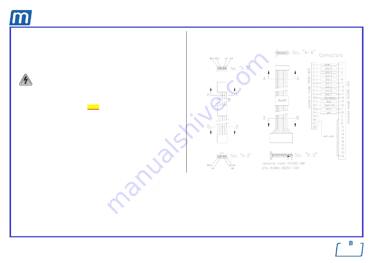
Mocom millennium B Скачать руководство пользователя страница 229


Rev. 1 


Card Gr5- 

5


PRINTER SIGNAL  

A#2BP2570000 


PRINTER POWER SUPPLY  

A#2BP2580000 


Before servicing, switch off the equipment and unplug the power 
supply cable from the mains socket  


1.  Remove the covers (see card 

Gr7-1

 ); 

2.  Disconnect the signal and power supply wirings from the printer, CPU board 

and printer board; 

3.  Replace the wiring, restore connections and assembly all items proceeding in 

reverse order as above;  

4.  Run a sterilization cycle. 


Содержание millennium B

Страница 1: ...Rev 1...

Страница 2: ...CTING DEMINERALIZER MILLDROP 16 CONNECTING AN EXTERNAL DRAIN TANK 17 DIRECT CONNECTION TO A CENTRALIZED DRAINING POINT 19 ACQUISITION AND UPDATING THE AMBIENT PRESSURE VALUES 20 CONFIGURATION 21 Gener...

Страница 3: ...by mode 56 Filling distilled water 57 Manual filling 57 Automatic filling 57 MAX level in the internal external drain tank 58 Emptying the internal tank 58 Emptying the external tank 58 MAINTENANCE 5...

Страница 4: ...d by the pointing finger WARNING This symbol indicates a potential danger of injury Follow the procedures described in the manual to avoid injuring the user and or others DANGER This symbol indicates...

Страница 5: ...ERTY DAMAGE OR INJURY IN THE EVENT THAT THE PRODUCT IS NOT INSTALLED OR USED CORRECTLY Please observe the following precautions in order to avoid injury or property damage Use ONLY distilled water of...

Страница 6: ...liability M O COM CUSTOMER SERVICE M O COM Ltd Co is completely available to customers to provide any technical information about the product as well as to offer suggestions and advice on steam steril...

Страница 7: ...ing all traces of humidity from any load Its exclusive steam generation system effective plumbing circuit and electronic management supplemented by high precision sensors guarantees high process execu...

Страница 8: ...output slot option on off switch Door micro switch Motorized door closing system Bacteriological filter Sterilization chamber Distilled water fill quick connector Used water drain quick connector Wat...

Страница 9: ...y thermostat and manual rearm Connection for directly draining the used water tank Connection for automatically filling the distilled water tank Steam generator safety thermostat and manual rearm Jack...

Страница 10: ...art Stop key Enter confirmation of the value option selected Sterilization cycle selection key Value increment Forward scroll of the menu options Test cycle selection key Value decrement Backward scro...

Страница 11: ...power 2300 W 10A Insulation class Class I Installation category Cat II Environment of use Internal use Noise level 60 db A max Environmental operating conditions Temperature 15 C 40 C Relative Humidi...

Страница 12: ...cut off of the electricity to the chamber heating element Door position safety microswitch Confirmation of the correct closing position of the door of the container under pressure Action signals wron...

Страница 13: ...VALUE 5 7 5 7 APPEARANCE colorless transparent without sediments colorless transparent without sediments HARDNESS 0 02 mmol l 0 02 mmol l e When purchasing distilled water always check that the quali...

Страница 14: ...the danger of physical injury or property damage not to mention malfunctions and damage to the machine So please follow the instructions in this chapter scrupulously e M O COM Customer Service will a...

Страница 15: ...vide a detailed description to the reseller and the transporter that made the delivery Content The package contains the following items steam sterilizer Stainless steel wire instrument tray 5 pcs Ref...

Страница 16: ...WE RECOMMEND THAT THE DEVICE BE TRANSPORTED AND STORED AT A TEMPERATURE NO LOWER THAN 5 C PROLONGED EXPOSURE TO LOW TEMPERATURE AN DAMAGE THE PRODUCT e Keep the original packaging and use it whenever...

Страница 17: ...he power cord is not bent or crushed It must run freely all the way to the socket Install the device that any external fill drain tubing is not bent or crushed They must run freely to the drain tank C...

Страница 18: ...a ground If it is necessary to replace the plug on the power cord use one with equal characteristics or at any rate adequate to the device s electrical characteristics The user is entirely responsible...

Страница 19: ...on tape or connector sealant for a perfect seal Use the filling tanks silicone tube or other suitable tube max length 2 m and insert it on the filling connector taking care to push it completely on Lo...

Страница 20: ...nstructions Connect the supplied water filling tube to the rear fitting point lock with clip Connect the supplied START STOP cable to the rear jack connector Switch on the MILLDROP Switch on the steri...

Страница 21: ...all the way on and lock it with the plastic tie Cut the silicone tube to measure push the free end on connector A on the drain tank and lock it with the plastic tie e Make sure the tube is not bent c...

Страница 22: ...e other end of the tube to the centralized draining point checking the seal e Make sure the tube is not bent crushed or obstructed in any way The following diagram provides an indicative arrangement o...

Страница 23: ...end on the connection provided on the centralized draining point and lock with the plastic tie or other means e Make sure the tube is not bent crushed or obstructed in any way The following diagram pr...

Страница 24: ...cquisition the ambient pressure is higher than a set value the system automatically updates the stored value after a brief delay Otherwise the data remains unchanged without updating After updating th...

Страница 25: ...e Customer Service by M O COM is available to help users by providing suggestions or advice on the best way to uses the options in the SETUP program Starting and entering the Setup Mode To start the...

Страница 26: ...ode the control panel keys have different functions than in normal mode Symbol Function ENTER confirm the selected option or value Symbol Increase the value scroll down Symbol Decrease the value scrol...

Страница 27: ...door open EXIT SETUP st by or RESUME SETUP time limited beep until door opening AMBIENTPRESSURE EXIT LCD CONTRAST Selected program see menu STND INTEL EXTRA long drying STND FAST short drying INTERNA...

Страница 28: ...ion programs shown on the LCD display STAND BY OPTIONS stand by mode settings PRINT OPTIONS setting printer and printing options FILLING OPTIONS setting modes for filling the distilled water tank DRAI...

Страница 29: ...vel menu e As soon as the selection is confirmed all the menus of the SETUP program will be displayed in the language set Setting the Date DATE SETTING on the BASIC menu When DATE SETTING is selected...

Страница 30: ...When PASSWORD is selected with the key you will see this menu D I S A B L E D A N Y P O W E R O N A N Y C Y C L E S T A R T E X I T Select DISABLED to use the device freely without any limitation on...

Страница 31: ...lowing screen is displayed I N S E R T P A S S W O R D t o e n t e r t o e x i t Enter the password with the and keys fixed length 8 characters Confirm with the key Then the following message will app...

Страница 32: ...oceed as follows 1 Select PROGRAMS using the key the following menu appears 1 s t P R E S E T 2 n d P R E S E T 3 r d P R E S E T 4 t h P R E S E T E X I T Define the position 1 2 3 or 4 to which the...

Страница 33: ...that allow selecting the type of drying to associate to the selected program a Programs with short drying HOLLOW SOLID EMERGENCY S T A N D A R D D R Y I N G F A S T D R Y I N G E X I T It is possible...

Страница 34: ...terilization intelligent drying may not work correctly with worse than expected results In these cases use the STANDARD or EXTRA options depending on the need When the EXTRA option is activated the fo...

Страница 35: ...m with a sterilization process at 121 C or 134 C for one at 134 C Move using the and keys and confirm with the key 2 You will then go the screen T I M E X X m i n t o s e t t o e n t e r t o e x i t U...

Страница 36: ...solid loose materials and even hollow so long as not wrapped Move with the and confirm with the key 5 Depending on the selection SHORT or LONG one of two different menus will open these menus are the...

Страница 37: ...ve e The list of available programs their screens and the characteristics of sterilizable materials in relation to the programs are reported in the section 2 e Access to a CUSTOM cycle does not requir...

Страница 38: ...ating level O F F L O W H I G H E X I T Select HIGH high preheating level for intense use or at any rate to reduce the wait time between one cycle and the next to a minimum Select LOW low preheating f...

Страница 39: ...ss consumption of electricity Set using the and keys confirm with the key e This option is also active with STAND BY OFF However in this condition the timer value obviously has no effect since the hea...

Страница 40: ...R I N T E R R E P O R T E X I T Select PRINTER to select the settings for the printer used or REPORT to set the number of copies to print and to reprint data from the last program executed a Item PRIN...

Страница 41: ...X I T Activate CR to use printers that advance the paper only on the CR Carriage Return command or CR LF for that require the CR LF Carriage Return Line Feed commands or with FF Form Feed for printer...

Страница 42: ...he end of the program The following text appears C O P I E S X X t o s e t t o e n t e r t o e x i t Set the number of copies desired up to a maximum of 5 Confirm with the key e In STEP BY STEP mode i...

Страница 43: ...vice see Chapter Installation After FILL OPTIONS is selected the following menu appears A U T O M A T F I L L I N G M A N U A L F I L L I N G E X I T When AUTOMATIC FILL is selected automatic filling...

Страница 44: ...E R N A L D R A I N E X T E R N A L D R A I N E X I T When INTERNAL DRAIN is enabled the reading of the MAX level sensor in the internal tank is enabled The EXTERNAL DRAIN command also activates the M...

Страница 45: ...llowing screen appears A C Q U I S I T I O N O F T H E A M B I E N T P R E S S U R E t o e n t e r t o e x i t e Check that the sterilizer door is completely OPEN If you try to acquire the pressure wi...

Страница 46: ...trast while the key decreases it Place yourself in your usual working position and adjust the contrast until the display is as clear and readable as possible ACTIVATING CONFIGURATION OPTIONS SERVICE M...

Страница 47: ...EV3 NO VACUUM CYCLE ELECTRIC FANS EV6 MANUAL EV1 SPECIAL CYCLE STEAM GENERATOR EV4 EXIT WATER PUMP EXIT EV2 CONTINUOUS CYCLE RESISTOR EV5 VACUUM PUMP DEVICE TEST TEST CYCLES MOCOM H2O CIRCUIT FACTORY...

Страница 48: ...he automatic test of the devices according to the following order LOCKING DEVICE WATER PUMP EV1 VACUUM PUMP EV2 AUXILIARY PUMP automatic water feeding EV3 STEAM GENERATOR EV4 RESISTOR heating EV5 ELEC...

Страница 49: ...ll test of the sterilizer As confirmed the choice exit from the Setup menu select a cycle and enter the START command The sterilizer will start an automatic sequence of any available cycle At the end...

Страница 50: ...I L L I N G O F T H E H 2 0 C I R C U I T t o a c t i v a t e t o e x i t As confirmed by the key the water pump starts making possible to check the hydraulic circuit Counter reset COUNTER RESET item...

Страница 51: ...nu This option allows to obtain the data printout of the history register stored in the sterilizer memory PT1 correction PT1 CORRECTION item on the SERVICE menu This option allows to set the Ohm value...

Страница 52: ...he terms shown see the paragraph Activating Configuration Options 1 s t P R E S E T 1 3 4 C P O R O S I S T A N D A R D D R Y I N G 2 n d P R E S E T 1 3 4 C H O L L O W F A S T D R Y I N G M I L L E...

Страница 53: ...T U P C O M P L E T E t o e x i t t o r e s u m e After several seconds the device returns to normal operation in STAND BY mode DEFAULT SETTING The sterilizer leaves the factory with the following set...

Страница 54: ...s regarding these aspects leaving the user to study the subject further in the most suitable way Treating the material before sterilization First of all it should be recalled that when handling and ma...

Страница 55: ...drying the instruments For handles turbines contra angles etc supplement the above with treatment in suitable dedicated devices that provide effective internal cleaning occasionally including lubrica...

Страница 56: ...gauze cloth to isolate and protect them Arrange recipients glasses cups test tubes etc resting on their side or upended so avoid pooling water Do not load trays beyond their indicated limit see Techni...

Страница 57: ...same metal Seal the wrapping with adhesive tape for autoclaves or heat sealing machines Do not use staples pins or other fasteners since they can compromise the maintenance of sterility Arrange the en...

Страница 58: ...e care not to cut or damage the wrappings 4 Let the instruments cool before any transport and subsequent storage If necessary for transport transfer the material using dry clean and disinfected contai...

Страница 59: ...control panel lights up and beeps so you can visually check its correct operation The panel then displays this message M I L L E N N I U M B R E x x x x B M y y y y y y D E V I C E C H E C K U P e If...

Страница 60: ...print the data and fill the tank please refer to the Chapter Configuring the device At regular intervals the first two lines on the display alternate with the modes set for printing ON OFF and filling...

Страница 61: ...cated on the side of the connector and detach the quick connector 9 Refill the container 2 l and repeat the operations described in points 2 3 and 4 a second time 10 When the MAX level icon comes on a...

Страница 62: ...free end of the supplied tube into the tank 2 Connect the quick connector to the corresponding female connector under the chamber entrance marked pushing until you hear a click 3 Wait for the complete...

Страница 63: ...hedule The table summarizes the maintenance required to keep the sterilizer operating at peak efficiency In the case of very intense use we recommend shortening maintenance intervals DAILY Clean the g...

Страница 64: ...The formation of white spots on the base of the internal walls of the sterilization chamber means that you are using low quality demineralized water BEFORE PERFORMING ORDINARY MAINTENANCE MAKE SURE TH...

Страница 65: ...ter tank 1 Arrange an empty container on the floor near the sterilizer and put the free end of a tube into it 2 Unscrew the plug 1 from the rear draining point and plug in the other end of the tube 3...

Страница 66: ...the water drain filter With use various residues will probably tend to accumulate inside the filter obstructing the lower drain tube over time For cleaning or replace the filter open the door of the s...

Страница 67: ...oll and place a new one so that the paper unrolls off the top use thermal paper roll width 57 mm diameter max 45 mm 4 unroll about 15 cm of paper and close the printer door 5 thread the paper in the s...

Страница 68: ...of the product The reference European standards EN 554 Sterilization of the medical devices Method for the validation and systematic control of the steam sterilization and EN 556 Sterilization of the...

Страница 69: ...15 3rd vacuum pulse PV3 16 3rd pressure pulse PP3 17 Thermodynamic equilibration 18 Process 19 Steam discharge 20 Drying 21 Ventilation 22 Levelling 23 Completion of the cycle 24 MANUAL CYCLE INTERRUP...

Страница 70: ...compressed air turbines or mechanical transmission counter angles tooth scalers etc Glass articles Mineral based articles Articles made of heat resistant plastic Articles made of heat resistant rubber...

Страница 71: ...hollow instruments in double package 1 50 0 50 0 25 For material and instruments in single and double packaging we recommend using the 3 tray configuration 134 C HOLLOW 134 2 10 4 S F S 30 33 525 0 7...

Страница 72: ...minutes vacuum drying typical of POROUS and WRAPPED cycles Short 4 minutes vacuum drying typical of HOLLOW and SOLID cycles 3 Access to a CUSTOM cycle does not require a password None of the combinat...

Страница 73: ...A S S W O R D t o e n t e r t o e x i t Enter the password using the and keys Confirm with the key The display does not offer any active preselection The device is waiting for the user to select a pro...

Страница 74: ...summary table the effectiveness of the sterilization process is NOT GUARANTEED RUNNING THE STERILIZATION PROGRAM General A sterilization cycle consists of a determined number of phases The number and...

Страница 75: ...TART see the Chapter Configuration Setting the password you will be asked to enter the access code Password check I N S E R T P A S S W O R D t o e n t e r t o e x i t Enter the password using the and...

Страница 76: ...interrupt the start command and return in Stand by mode In case of the card memory full or insufficient to store the new cycle data the following message will be displayed W A R N I N G C F C A R D F...

Страница 77: ...lower lines of the display will show the following parameters Pressure of the sterilization chamber bar Temperature of the sterilization chamber C Progressive time of the sterilization cycle mm ss 1 1...

Страница 78: ...cle relating the program 134 C POROUS preset 1 on the control panel provided with fractionated pre vacuum Standby status C o u n t e r x x x x x y y y y y S t a n d b y H I G H 2 3 6 c 3 0 0 8 0 2 0 0...

Страница 79: ...ber to temperature required for starting the cycle The display shows the following 1 1 3 4 C P O R O U S W A R M U P 2 3 9 C 0 0 1 b a r 0 0 0 0 CHAMBER Water tank DESCRIPTION STATUSES PV PA EV1 no EV...

Страница 80: ...P O R O U S 1 V A C U U M P U L S E 8 4 1 C 0 6 9 b a r 0 1 2 5 CHAMBER Water tank DESCRIPTION STATUSES P t VP WP EV1 no EV2 nc EV3 nc EV4 EV5 no EV6 nc Fan from 0 00 to 0 70 bar ON OFF OFF OFF ON ON...

Страница 81: ...1 P R E S S U R E P U L S E 1 0 8 0 C 0 4 7 b a r 0 3 5 8 CHAMBER Water tank DESCRIPTION STATUSES P t VP WP EV1 no EV2 nc EV3 nc EV4 EV5 no EV6 nc Fan 1 st pressure pulse from 0 88 to 0 50 bar from 0...

Страница 82: ...0 6 CHAMBER Water tank DESCRIPTION STATUSES P t VP WP EV1 no EV2 nc EV3 nc EV4 EV5 no EV6 nc Fan Steam discharge from 1 00 to 0 22 barr OFF OFF ON OFF ON OFF ON OFF ON Transition phase of the chargin...

Страница 83: ...in pressure 2nd PRESSURE PULSE 1 1 3 4 C P O R O U S 2 P R E S S U R E P U L S E 1 1 4 C 0 7 2 b a r 0 7 4 4 CHAMBER Water tank DESCRIPTION STATUSES P t VP WP EV1 no EV2 nc EV3 nc EV4 EV5 no EV6 nc Fa...

Страница 84: ...DESCRIPTION STATUSES P t VP WP EV1 no EV2 nc EV3 nc EV4 EV5 no EV6 nc Fan Steam discharge from 1 00 to 0 22 bar OFF OFF ON OFF ON OFF ON OFF ON Transition phase of the charging circuit 1 ON OFF ON OF...

Страница 85: ...PRESSURE PULSE always through the injection of steam 1 1 3 4 C P O R O U S 3 P R E S S U R E P U L S E 1 2 8 6 C 1 7 0 b a r 1 2 3 3 CHAMBER Water tank DESCRIPTION STATUSES P t VP WP EV1 no EV2 nc EV...

Страница 86: ...low the temperature in the chamber and the load to stabilize EQUILIBRATION The liquid crystal display shows 1 1 3 4 C P O R O U S E Q U I L I B R A T I O N 1 3 5 4 C 2 1 5 b a r 1 3 4 0 CHAMBER Water...

Страница 87: ...e reason the sterilization cycle has been interrupted before completion the icon continues flashing If for some reason the sterilization cycle has been interrupted before completion the icon continues...

Страница 88: ...U S D E P R E S S U R I Z A T I O N 1 2 3 9 C 1 2 4 b a r 1 8 2 0 The icon for the sterilization process status is steady on Water tank DESCRIPTION STATUSES P t VP WP EV1 no EV2 nc EV3 nc EV4 EV5 no...

Страница 89: ...will appear 1 1 3 4 C P O R O U S D R Y I N G N O R 1 0 1 1 C 0 0 0 b a r 1 8 5 1 1 1 3 4 C P O R O U S D R Y I N G I N T 1 0 1 1 C 0 0 0 b a r 1 8 5 1 1 1 3 4 C P O R O U S D R Y I N G X X 1 0 1 1 C...

Страница 90: ...r is injected while maintaining a vacuum in the chamber to eliminate condensate and cool the load 1 1 3 4 C P O R O U S V E N T I L A T I O N 8 4 4 C 0 7 7 b a r 2 6 5 1 Water tank DESCRIPTION STATUSE...

Страница 91: ...P O R O U S L E V E L L I N G 8 6 9 C 0 4 3 b a r 2 9 2 1 CHAMBER Water tank DESCRIPTION STATUSES P t VP WP EV1 no EV2 nc EV3 nc EV4 EV5 no EV6 nc Fan Levelling pressure from 0 45 to 0 10 bar 0 10 bar...

Страница 92: ...tically produced if the printer is installed and selected Check and sign this report file it in a suitable place Refer to the Print report examples e At the end of the cycle and up to the opening of t...

Страница 93: ...r 2 6 0 1 When safe conditions are reached the machine activates a special procedure first asking the user to manually unlock the door by displaying the following instruction P R E S S T O U N L O C...

Страница 94: ...escription of the alarms see Alarm indication After a program is manually interrupted MANUAL STOP always check the status of the icon before using the material in the sterilization chamber If the icon...

Страница 95: ...ations for a further confirmation of the good outcome of the sterilization process The operator should sign in the space provided and file the document for possible future use If necessary copies of t...

Страница 96: ...Ver SW Exxxx BMyyyyyy Counter 0007 0015 Selection 134c POROUS Temperature 134 C Pressure 2 10 Bar Process t ime 4 min Stand by HIGH Pre vacuum FRACTIONATED Drying STANDARD CYCLE START 19 11 02 09 52 T...

Страница 97: ...6 6 109 6 095 7 01 27 047 8 0 78 149 3 107 7 095 7 01 57 047 8 0 80 155 3 105 8 095 4 02 07 076 5 0 57 149 9 105 2 095 1 02 17 081 1 0 49 142 1 104 6 094 6 08 15 068 4 0 76 151 8 104 7 102 3 08 22 061...

Страница 98: ...ing the perfect seal of the sterilizer s entire plumbing system By measuring the variation in the degree of vacuum in a certain span of time and comparing it with pre set limit values it is possible t...

Страница 99: ...ogous to what is described in the Chapter Sequence of the process At the end of the program remove the test device open the capsule and remove the indicator from its housing If the steam has correctly...

Страница 100: ...easured during the Vacuum Test the system is programmed to prevent its execution when the temperature sensors of the sterilization chamber shows a value higher than 50 C If you try to start the progra...

Страница 101: ...same as described for a standard sterilization cycle The vacuum phase begins immediately and the display reads V A C U U M T E S T V A C U U M P U L S E 0 6 9 b a r 0 1 0 2 The display shows the press...

Страница 102: ...rought back to atmospheric pressure V A C U U M T E S T L E V E L L I N G 0 2 9 b a r 1 7 1 9 When the program finishes the display will read V A C U U M T E S T T E S T P A S S E D 0 0 1 b a r 1 7 4...

Страница 103: ...4c POROUS 134 C 4 00 Pressure bar 0 00 1 00 2 00 2 10 0 80 Time min LONG DRYING PROCESS PRE VACUUM PROGRAM 134c PRION 134 C 18 00 121 POROUS 0 00 1 00 1 10 Pressure bar Time min LONG DRYING PROCESS FR...

Страница 104: ...34c HOLLOW 134 C 4 00 Pressure bar 0 00 1 00 2 00 2 10 1 00 Time min SHORT DRYING PROCESS FRACTIONATED PRE VACUUM 0 80 121 HOLLOW PROGRAM 121c HOLLOW 121 c 20 00 0 00 1 00 1 00 Time min SHORT DRYING P...

Страница 105: ...34c WRAPPED 134 C 4 00 Pressure bar 0 00 1 00 2 00 2 10 1 00 Time min LONG DRYING PROCESS ONE SHOT PRE VACUUM 121 WRAPPED PROGRAM 121c WRAPPED 121 C 20 00 Pressure bar 0 00 1 00 1 10 1 00 Time min LON...

Страница 106: ...134c SOLID 134 C 4 00 Pressure bar 0 00 1 00 2 00 2 10 1 00 Time min SHORT DRYING PROCESS ONE SHOT PRE VACUUM 134 SOLID PROGRAM 121c SOLID 121 C 20 00 Pressure bar 0 00 1 00 1 00 Time min SHORT DRYING...

Страница 107: ...n DRYING PROCESS ONE SHOT PRE VACUUM XXX CUSTOM PROGRAM XXXc CUSTOM 134 C da 4 00 a 30 00 121 C da 20 00 a 30 00 Pressure bar 0 00 1 00 2 00 2 10 1 00 Time min SETUP ONE SHOT PRE VACUUM or FRACTIONATE...

Страница 108: ...ROCESS FRACTIONATED PRE VACUUM VACUUM TEST PROGRAM VACUUM TEST VT 0 80 bar Pressure bar P0 0 00 1 00 Time min 0 80 t1 t2 t1 300 s 5 minutes 10 minutes P1 P2 P3 P2 P1 P0 P1 10 t3 t2 600 s WAITING LEAKA...

Страница 109: ...RD ALARM LIST H CODES 10 E 000 11 E 010 13 E 020 14 E 021 17 E 030 18 E 031 19 E 041 20 E 900 21 E 901 22 E 902 23 E 999 25 A 022 26 A 023 27 A 024 28 A 032 29 A 040 30 A 040 continue 31 A 101 32 A 10...

Страница 110: ...65 H 410 66 H 990 67 H 991 68 H 992 69 H 993 70 REPAIR PROCEDURES 71 GROUP 1 ELECTRONIC DEVICES AND ASSEMBLIES GROUP 2 ELECTROVALVES GROUP 3 PUMPS GROUP 4 PLUMBING CIRCUIT GROUP 5 WIRINGS GROUP 6 DOO...

Страница 111: ...Code format Hxxx xxx identifying number 000 999 ALARM INTERVENTION e In the case of an alarm please only remove voltage from the device after executing a reset see System reset The intervention of the...

Страница 112: ...A l a r m M e s s a g e C I R C U I T C L E A N I N G 1 0 0 6 C X X X X 0 7 0 b a r 1 1 4 0 At the end of what has been described and having reached safe conditions the machine activates a special pro...

Страница 113: ...be printed for the interrupted sterilization program and the alarm that intervened Check the document initial it in the space provided and file it in a suitable place Refer to Print report examples Al...

Страница 114: ...TING THE SYSTEM The system is RESET in two alternative ways depending on the alarm that occurred 1 Press the PROGRAM SELECTION key for about 3 seconds A beep confirms the RESET Never turn the device o...

Страница 115: ...ening DOOR LOCKED E 030 Water in the fill tank at minimum MIN level WATER MIN E 031 Water in the drain tank at maximum MAX level EXHAUST MAX E 041 Filling the tank too frequently automatic filling FIL...

Страница 116: ...LING PROBLEM A 101 PT1 broken sterilization chamber PTC BROKEN A 102 PT2 broken steam generator PTC BROKEN A 103 PT3 broken heating element PTC BROKEN A 104 PT4 broken sterilization chamber wall PTC B...

Страница 117: ...ut PV2 TIMEOUT A 254 2nd rise to ambient pressure not reached within timeout ATM2 TIMEOUT A 255 2nd pressure pulse not reached within timeout PP2 TIMEOUT A 256 3rd vacuum pulse not reached within time...

Страница 118: ...mit Phase PROCESS T OVER LIMIT H 403 Temperature below MIN limit Phase PROCESS T UNDER LIMIT H 404 Temperature fluctuating over the limit Phase PROCESS PT1 FLUCTUATING H 405 Pressure above MAX limit P...

Страница 119: ...le Mains fuses blown Replace the burned fuse 16A switch on the equipment open the door and follow the instructions on the LCD Reset the alarm and repeat the sterilization cycle Pay attention during th...

Страница 120: ...solution One or both the steam generator cartridges failed Check the steam generator cartridge Replace the failed cartridge see card Gr1 19 Band heater in short circuit Check the band heater replace...

Страница 121: ...Replace the positioner see card Gr6 4 The door opens by oneself Adjust the positioner see Attachment A Replace the positioner see card Gr6 4 After the door gasket replacement the door rebounds Call t...

Страница 122: ...or for the correct procedure to start the cycle If the mechanism operates correctly and the LCD shows the alarm Check the integrity of the release micro switch Replace the release micro switch see car...

Страница 123: ...wiring see card Gr5 3 Check the board connector Replace the tip of the motor wiring Check the pressure switch Disconnect and connect again the pressure switch wiring Replace the pressure switch see c...

Страница 124: ...see card Gr6 6 Check for the free turning of the fork bushes Replace the blocked bush see card Gr6 3 Check that the motor runs normally The locking mechanism is step working Replace the pin see card G...

Страница 125: ...not open Check the 1 25 A fuse Replace the fuse see card Gr1 16 Check the pressure switch Disconnect and connect again the pressure switch wiring Replace the pressure switch see card Gr1 5 Disassembl...

Страница 126: ...re of the float wiring Restore the float wiring Failure of the float Replace the float see card Gr4 2 Check the wiring of the level sensor for the external used water tank Disconnect the wiring on the...

Страница 127: ...Gr4 2 Check the wiring of the water level sensor for the external used water tank Disconnect the wiring on the CPU board Check the water level sensor connection on the CPU board Restore the connection...

Страница 128: ...and sterilizer Replace the external pipe Check that the entry filter is not dirty Replace the entry filter Check for possible break of the internal pipe Replace the internal pipe Check that the water...

Страница 129: ...r an alarm occurring Clean carefully the gasket and the parabola s board try a new Vacuum test Leakage from the door gasket Replace the gasket see card Gr6 1 Find the valve and clean it Leakage from a...

Страница 130: ...a valve Replace the valve causing the problem see cards Gr2 Check that the Vacuum test was not launched with chamber too hot Advise to carry out the Vacuum test at the beginning of the working day wi...

Страница 131: ...Vacuum test Fasten the dowel of the internal rod by a sealant see card Gr3 3 Replace the large membranes see card Gr3 3 Vacuum pump running in irregular way and is very noisy Clean the vacuum pump The...

Страница 132: ...xchanger Replace the heat exchanger see card Gr4 3 Leakage from the pressure transducer pipe Remove and connect again the pipe on the pressure transducer reset the alarm and try a new Vacuum test Pres...

Страница 133: ...START STOP key pushed for more than 3 during the cycle process The user pushed the START STOP key Advice the user to do not use the manual stop function when you need to load an additional items to b...

Страница 134: ...ce the micro switch see card Gr6 5 Replace the micro switch see card Gr6 5 At the switching on with door closed the wheel pin micro switch is broken Go to Attachment H or Attachment I Release the micr...

Страница 135: ...ignaling Possible cause Check Proposed solution LOCKING PROBLEM Failure on the micro switches ON ON During the initial self test the two micro switches are OFF Blackout during the opening Power supply...

Страница 136: ...d the opening micro switch is OFF Locking mechanism fuse burned during a cycle Go to Attachment H or Attachment I Go to Attachment H or Attachment I Alarm occurred during the previous cycle sterilizer...

Страница 137: ...Connector of the water level floats unplugged from the board Restore the right connection The board does not correctly read the signals from the water level floats Replace the CPU board see card Gr1 1...

Страница 138: ...in open position Open the tap in the external filling tank Check for possible obstruction in the external filling tank pipe Free the external filling tank pipe and shorten it if too long Check for po...

Страница 139: ...in the water pump wiring connection Restore the right connection of the water pump wiring Leak in the internal pipe Replace the broken pipe Perforation in the main tank Replace the main tank see card...

Страница 140: ...the display If the room temperature turn off and on the sterilizer more times Replace PT1 see card Gr1 8 If differs for many C turn off and on the sterilizer more times Replace PT1 see card Gr1 8 Res...

Страница 141: ...see card Gr4 6 Steam generator clogged Advice the user to change the type of distilled water used for the sterilization Fill the main tank Replace the water pump see card Gr3 1 No water feeding the s...

Страница 142: ...oposed solution Check the calibration Perform the PT2 calibration see Attachment M Complete sterilizer calibration see Attachment N Replace the CPU board see card Gr1 1 Reset or failure on the data me...

Страница 143: ...on the display If the room temperature turn off and on the sterilizer more times Replace PT3 see card Gr1 10 If differs for many C turn off and on the sterilizer more times Replace PT3 see card Gr1 10...

Страница 144: ...on the display If the room temperature turn off and on the sterilizer more times Replace PT4 see card Gr1 11 If differs for many C turn off and on the sterilizer more times Replace PT4 see card Gr1 1...

Страница 145: ...he wiring of the level sensor for the external used water tank Disconnect the wiring on the CPU board Check the ground connection of the sterilizer Clean the ground connections Replace the damage grou...

Страница 146: ...he wiring of the level sensor for the external used water tank Disconnect the wiring on the CPU board Check the ground connection of the sterilizer Clean the ground connections Replace the damage grou...

Страница 147: ...he wiring of the level sensor for the external used water tank Disconnect the wiring on the CPU board Check the ground connection of the sterilizer Clean the ground connections Replace the damage grou...

Страница 148: ...the wiring of the level sensor for the external used water tank Disconnect the wiring on the CPU board Check the ground connection of the sterilizer Clean the ground connections Replace the damage gro...

Страница 149: ...y thermostat Restore the safety thermostat and repeat the sterilization cycle Steam generator clogged Replace the lower section of the steam generator see card Gr4 6 Fault in the board Replace the boa...

Страница 150: ...wiring of the vacuum pump reset the alarm and repeat the sterilization cycle Fixe by sealant the grain of the connecting rod on the vacuum pump see card Gr3 3 Replace the larger membranes of the vacu...

Страница 151: ...water drain hole into the chamber Clean by using compressed air Check the steam generator Replace the Saeco filter see card Gr4 8 Replace the water pump see card Gr3 1 Replace valve EV6 see card Gr3...

Страница 152: ...ge 3 44 LCD INDICATION Alarm description Effect Signaling Possible cause Check Proposed solution Air leakage from fitting Seal the fitting Check the integrity of the chamber Replace the sterilization...

Страница 153: ...Fault in the pipe connecting the steam generator Replace the pipe Sterilization chamber overloaded Advice the operator for properly loading of the sterilization chamber Restore the safety thermostat a...

Страница 154: ...properly the gasket and the parabola board Steam leakage from the door gasket Replace the door gasket see card Gr6 1 Identify the valve and clean it Steam leakage from a valve Replace the valve causi...

Страница 155: ...e the wiring of the vacuum pump reset the alarm and repeat the sterilization cycle Fixe by sealant the grain of the connecting rod on the vacuum pump see card Gr3 3 Replace the larger membranes of the...

Страница 156: ...calibrated Send the sterilizer to the Mocom Service department Check the type and the mass of the load arranged in the chamber Advice the user on loading and arranging the material in the chamber as i...

Страница 157: ...lt in the pipe connecting the steam generator Replace the pipe Sterilization chamber overloaded Advice the operator for properly loading of the sterilization chamber Restore the safety thermostat and...

Страница 158: ...lly the gasket and the parabola borad reset the alarm and restart the cycle Steam leakage from the door gasket Replace the door gasket see card Gr6 1 Identify the valve and clean it Steam leakage from...

Страница 159: ...re the wiring of the vacuum pump reset the alarm and repeat the sterilization cycle Fixe by sealant the grain of the connecting rod on the vacuum pump see card Gr3 3 Replace the larger membranes of th...

Страница 160: ...calibrated Send the sterilizer to the Mocom Service department Check the type and the mass of the load arranged in the chamber Advice the user on loading and arranging the material in the chamber as i...

Страница 161: ...n the pipe connecting the steam generator Replace the pipe Sterilization chamber overloaded Advise the operator for properly loading of the sterilization chamber Restore the safety thermostat and repe...

Страница 162: ...lean properly the gasket and the parabola board Steam leakage from the door gasket Replace the door gasket see card Gr6 1 Identify the valve and clean it Steam leakage from a valve Replace the valve c...

Страница 163: ...am generator safety thermostat Replace the safety thermostat see card Gr1 12 Clean properly the gasket and the parabola board Steam leakage from the door gasket Replace the door gasket see card Gr6 1...

Страница 164: ...lem on switching the valves during the steam discharge EV3 interrupted Replace the EV3 shaft see card Gr2 3 EV3 Shaft blocked EV3 dirty Clean or replace the shaft see card Gr2 3 Replace the wiring Rep...

Страница 165: ...cer broken Pressure reading by the transducer higher than 2 35 bar Fault in the wiring connecting the pressure transducer to board Fault in the pressure transducer Steam leakage from the pressure tran...

Страница 166: ...Replace the pressure transducer see card Gr1 4 Seal the pipe fitting Steam leakage from the pressure transducer Replace the pressure transducer see card Gr1 4 Fault in the pressure transducer Replace...

Страница 167: ...ctly Replace EV6 see card Gr3 1 Identify the valve causing the problem and clean it Steam leakage from a valve Replace the valve causing the problem see cards Gr2 The discharge valve does not open cor...

Страница 168: ...eplace EV6 see card Gr3 1 Replace the lower section of the steam generator see card Gr4 6 Steam generator clogged Different distilled water must be used Stored calibration values changed Send the ster...

Страница 169: ...clogged Different distilled water must be used Replace the water pump see card Gr3 1 Problem in the water pump of the steam generator Replace the fuse see card Gr1 16 EV6 valve does not open correctly...

Страница 170: ...team generator Problem in the steam generator Replace the lower section of the steam generator see card Gr4 6 Steam leakage from the hydraulic circuit Identify the component and replace it Fault in th...

Страница 171: ...Identify the valve and clean it Steam leakage from a valve Replace the valve causing the problem see cards Gr2 Steam leakage from a pipe Replace the pipe causing the problem Problem in the water pump...

Страница 172: ...depending on the cycle type 121 or 134 C Fault in the board Replace the CPU board see card Gr1 1 Stored calibration values changed Send the sterilizer to the Mocom Service department Clean the valve...

Страница 173: ...nerator see card Gr4 6 Steam generator clogged Different distilled water must be used Fault in the board Replace the CPU board see card Gr1 1 Clean properly gasket and parabola board Steam leakage fro...

Страница 174: ...TION Alarm description Effect Signaling Possible cause Check Proposed solution TIMER PROBLEM Wrong hold time during the process phase Countdown time mismatches the setpoint value CPU board failed Repl...

Страница 175: ...ER PRESSURE Overpressure in the sterilization chamber Pressure value greater than 2 32 bar Fault in the board Replace the CPU board see card Gr1 1 Fault in the pressure transducer Replace the pressure...

Страница 176: ...e value greater than 138 C Fault in the board Replace the CPU board see card Gr1 1 Fault in the pressure transducer Replace the pressure transducer see card Gr1 4 Stored calibration values changed Sen...

Страница 177: ...ts a temperature value greater than 230 C Fault in the board Replace the CPU board see card Gr1 1 Fault in the pressure transducer Replace the pressure transducer see card Gr1 4 Steam generator clogge...

Страница 178: ...on OVERHEATING PT3 PT3 overheating PT3 detects a temperature value greater than 160 C Fault in the board Replace the CPU board see card Gr1 1 Fault in the pressure transducer Replace the pressure tran...

Страница 179: ...The repair procedures consist of cards grouped as follows GROUP 1 ELECTRONIC DEVICES AND ASSEMBLIES GROUP 2 ELECTROVALVES GROUP 3 PUMPS GROUP 4 PLUMBING CIRCUIT GROUP 5 WIRINGS GROUP 6 DOOR LOCKING ME...

Страница 180: ...3 KEYBOARD 4 PRESSURE TRANSDUCER 5 PRESSURE SWITCH 6 FIRMWARE FLASH EPROM 7 TRANSFORMER 8 PT1 PROBE 9 PT2 PROBE 10 PT3 PROBE 11 PT4 PROBE 12 STEAM GENERATOR THERMOSTAT 13 CHAMBER HEATER THERMOSTAT 14...

Страница 181: ...mains socket 1 Remove the covers see card Gr7 1 2 Unplug connectors and wirings from the board 3 Remove the screws fixing the board 4 Mount the new board restore connections and assembly all items pro...

Страница 182: ...cket 1 Remove the covers see card Gr7 1 2 Unplug connectors and wirings from the board 3 Remove the screws fixing the board 4 Mount the new board restore connections and assembly all items proceeding...

Страница 183: ...s of the front cover and move it as much as possibile from the frame see card Gr7 3 2 Remove the interface connector from CPU board 3 Access the fixing screws and remove the LCD display 1 4 Remove the...

Страница 184: ...e mains socket 1 Remove the covers see card Gr7 1 2 Remove the keyboard flat cable from the CPU board 3 Detach carefully the keyboard 1 4 Remove the protective film from the new keyboard 5 Attach the...

Страница 185: ...e pressure transducer wiring from the CPU board 3 Withdraw the pipe from the pressure transducer 4 Remove the nut 1 fixing the pressure transducer to the bracket 5 Remove the pressure transducer 6 Mou...

Страница 186: ...y cable from the mains socket 1 Remove the covers see card Gr7 1 2 Remove the wiring from the pressure switch 3 Remove the two screws fixing the pressure switch to the plate 4 Mount the new pressure s...

Страница 187: ...1 2 Remove carefully the two EPROM s 3 Replace EPROM s observing the mounting orientation 4 Plug off the jumper X21 5 Switch on the unit 6 Release Software update will appear on the LCD followed by t...

Страница 188: ...rom the boards 3 Remove the grid 1 from the rear frame to access the mounting screws of the transformer bracket 4 Remove the bracket with the transformer and unscrew the fixing screw 3 maintaining the...

Страница 189: ...left side of the machine and rear side of the chamber 6 Remove the nut and PT1 from its seat 7 Measure the ohm value of the new PT1 and write the value on the next row of the label attached on the rig...

Страница 190: ...r no 2 to be used on the new probe 4 Access to the left side of the machine and withdraw the wiring up to the thermal device 5 Remove the nut and PT2 from its seat 6 Measure the ohm value of the new P...

Страница 191: ...o be used on the new probe 4 Access to the left side of the machine and withdraw the wiring up to the thermal device 5 Unlock the spring 1 of the chamber s insulation layer to access the PT3 fixing 6...

Страница 192: ...CPU board 3 Remove the cable marker no 4 to be used on the new probe 4 Access to the left side of the machine and rear side of the chamber 5 Remove the nut and the PT4 withdraw the probe from the cham...

Страница 193: ...frame see card Gr3 1 3 Remove the steam generator see card Gr4 6 4 Unscrew the cap 1 and the screws from the rear frame 5 Remove the support 2 and thermal insulation layer 3 of the steam generator to...

Страница 194: ...cap 1 and the screws from the rear frame 3 Access to the left side of the frame and withdraw the cable up to the probe 4 Unlock the spring 2 on the insulation layer to access the he probe s bulb 5 Lo...

Страница 195: ...overs see card Gr7 1 2 Remove the clamp 1 from the sheath 2 of the fuse holder move the sheath to access the wiring then disconnect it from the fuse holder 3 Unscrew the cap with the fuse 3 and remove...

Страница 196: ...00 Before servicing switch off the equipment and unplug the power supply cable from the mains socket 1 Remove the cap 1 by using a flat screwdriver 2 Remove the fuse 2 3 Replace the fuse same type and...

Страница 197: ...ing and assembly all items proceeding in reverse order as above 4 Run a sterilization cycle GAM version F1 T 5A 250V trafo s secondary winding 24V F2 T 2A 250V 5V digital circuit 12V analogue circuit...

Страница 198: ...unplug the power supply cable from the mains socket 1 Remove the covers see card Gr7 1 2 Remove the wiring 1 from the switch 3 Remove the mains switch 2 4 Mount the new switch restore connections and...

Страница 199: ...1 4 Remove the thermostat probe 2 from the heater see card Gr1 13 5 Remove PT3 probe 3 see card Gr1 10 6 Remove the insulation layer covering the chamber heater 7 Disconnect the heater wiring from th...

Страница 200: ...see card Gr3 1 3 Remove the cartridge wiring from the power board 4 Remove the steam generator see card Gr4 6 5 Remove the support and the thermal insulation of the steam generator 6 Loosen the screw...

Страница 201: ...m the mains socket 1 Remove the covers see card Gr7 1 2 Remove the power 1 and interface 2 wiring from the printer unit 3 Unscrew the rear fixing screw 3 and remove the printer 4 4 Mount the new print...

Страница 202: ...Rev 1 Gr2 INDEX GROUP 2 ELECTROVALVES EV1 VALVE 1 EV2 VALVE 2 EV3 VALVE 3 EV4 VALVE 4 EV5 VALVE 5...

Страница 203: ...able from the mains socket 1 Remove the covers see card Gr7 1 2 Remove the wiring and the sheathed pipes from the valve 3 Remove the rear screws and the EV1 assembly 4 Disassembly the group as necessa...

Страница 204: ...power supply cable from the mains socket 1 Remove the covers see card Gr7 1 2 Remove the wiring and the sheathed pipes from the valve 3 Remove the group EV2 EV3 from the support 4 Disassembly the grou...

Страница 205: ...power supply cable from the mains socket 1 Remove the covers see card Gr7 1 2 Remove the wiring and the sheathed pipes from the valve 3 Remove the group EV2 EV3 from the support 4 Disassembly the grou...

Страница 206: ...y cable from the mains socket 1 Remove the covers see card Gr7 1 2 Remove the wiring and the sheathed pipes from the valve 3 Remove the EV4 group from the support 4 Disassembly the group as necessary...

Страница 207: ...cable from the mains socket 1 Remove the covers see card Gr7 1 2 Remove the wiring and the sheathed pipes from the valve 3 Remove the EV5 group from the rear frame 4 Disassembly the group as necessary...

Страница 208: ...Rev 1 Gr3 INDEX GROUP 3 PUMPS STEAM GENERATOR WATER PUMP 1 AUTOMATIC WATER FILLING PUMP 2 VACUUM DOUBLE PUMP 3...

Страница 209: ...the covers see card Gr7 1 2 Empty the main reservoir by removing the bottom plug 3 Remove the transparent and sheathed pipes 1 and 2 4 Remove the wiring from the pump 5 Remove the clamps 3 fixing the...

Страница 210: ...cket 1 Remove the covers see card Gr7 1 2 Remove the pipes and the wiring from the automatic water feeding pump 3 Remove the screws fixing the water pump assembly to the rear frame 4 Disassembly the p...

Страница 211: ...rom the mains socket 1 Remove the covers see card Gr7 1 2 Remove from the bottom frame the screws fixing the vacuum pump 3 Remove the sheathed pipes and the wiring from the pump 4 Remove the pump and...

Страница 212: ...GROUP 4 PLUMBING CIRCUIT WATER TANK 1 WATER LEVEL PROBES 2 HEAT EXCHANGER 3 ELECTRIC FAN 4 HEAT EXCHANGER 5 STEAM GENERATOR 6 BACTERIOLOGICAL FILTER 7 SAECO FILTER 8 LP1 FILTER 9 PIPES AND FITTINGS 10...

Страница 213: ...e card Gr7 1 2 Empty both reservoirs 3 Remove the wiring from the water level probes and the rear pipes from the reservoirs 4 Remove the right 1 and left 2 rail 5 Remove screws 3 fixing the reservoir...

Страница 214: ...from the mains socket 1 Remove the covers see card Gr7 1 2 Remove the wiring of the water level probe from the CPU board 3 Maintaining steady the probe body loosen the ring nut and remove the probe 4...

Страница 215: ...ins socket 1 Remove the covers see card Gr7 1 2 Remove the rear grid 1 3 Move out the group as possible and remove the sheathed pipes 4 Separate the heat exchanger 3 from the its frame 2 5 Mount the n...

Страница 216: ...emove the covers see card Gr7 1 2 Remove the rear grid 1 3 Move out the group as possible and remove the sheathed pipes and the fan wiring from the CPU board 4 Remove the cap 2 and remove the fan 3 5...

Страница 217: ...y cable from the mains socket 1 Remove the covers see card Gr7 1 2 Remove rear grid 1 3 Move out the group 2 as possible and remove the sheathed pipes and the fan wiring from the CPU board 4 Mount the...

Страница 218: ...rews and move out the steam generator as possible 5 Remove the steam generator from its support 1 and remove the thermal insulation layer 6 Remove the bulb of the thermostat 2 7 Loosen the screws and...

Страница 219: ...CTERIOLOGICAL FILTER 472 00010000 Before servicing switch off the equipment and unplug the power supply cable from the mains socket 1 Open the service door 2 Unscrew the bacteriologic filter 3 Replace...

Страница 220: ...ug the power supply cable from the mains socket 1 Remove the covers see card Gr7 1 2 Empty the distilled water reservoir 3 Cut the nylon clamp on the Saeco filter 1 and remove it 4 Mount the new filte...

Страница 221: ...e filter from the support and carefully clean it under a throw of running water using if necessary a pointed tool to remove possible material of greater dimensions 4 If the filter cannot be reused rep...

Страница 222: ...performed by taking care to follow the previous pipe path in order to not change its performance Fasten the pipe with plastic clips SHEATHED PIPES The replacement of sheathed pipes should be performed...

Страница 223: ...supply cable from the mains socket 1 Remove the covers see card Gr7 1 2 Remove the sheathed pipe from the safety valve fitting 3 Remove the safety valve assembly 1 4 Remove the safety valve 2 from th...

Страница 224: ...X GROUP 5 WIRING WATER PUMPS 1 VACUUM PUMP 2 DOOR MICROSWITCH 3 ELECTROVALVES 4 PRINTER 5 MOTOR AND PRESSURE SWITCH 6 STEAM GENERATOR GROUND WIRE 7 CHAMBER GROUND WIRE 8 MAINS SWITCH 9 POWER SUPPLY 10...

Страница 225: ...t and unplug the power supply cable from the mains socket 1 Remove the covers see card Gr7 1 2 Disconnect the wiring from the water pumps and power board 3 Replace the wiring restore connections and a...

Страница 226: ...t and unplug the power supply cable from the mains socket 1 Remove the covers see card Gr7 1 2 Disconnect the wiring from the vacuum pump and power board 3 Replace the wiring restore connections and a...

Страница 227: ...nt and unplug the power supply cable from the mains socket 1 Remove the covers see card Gr7 1 2 Disconnect the wiring from the micro switches and power board 3 Replace the wiring restore connections a...

Страница 228: ...and unplug the power supply cable from the mains socket 1 Remove the covers see card Gr7 1 2 Disconnect the wiring from the electro valves and power board 3 Replace the wiring restore connections and...

Страница 229: ...ent and unplug the power supply cable from the mains socket 1 Remove the covers see card Gr7 1 2 Disconnect the signal and power supply wirings from the printer CPU board and printer board 3 Replace t...

Страница 230: ...from the mains socket 1 Remove the covers see card Gr7 1 2 Remove the cover plate under the frame to access the ratio motor 3 Disconnect the wiring from the ratio motor pressure switch and power boar...

Страница 231: ...power supply cable from the mains socket 1 Remove the covers see card Gr7 1 2 Remove the steam generator see card Gr4 6 3 Disconnect the grounding wire from the steam generator and frame 4 Replace the...

Страница 232: ...nplug the power supply cable from the mains socket 1 Remove the covers see card Gr7 1 2 Disconnect the grounding wire from the mounting bracket of the chamber and frame 3 Replace the wiring restore co...

Страница 233: ...unplug the power supply cable from the mains socket 1 Remove the covers see card Gr7 1 2 Disconnect the wire from the mains switch fuse and mains filter board 3 Replace the wiring restore connections...

Страница 234: ...pment and unplug the power supply cable from the mains socket 1 Remove the covers see card Gr7 1 2 Disconnect the wire from the power and filter boards 3 Replace the wiring restore connections and ass...

Страница 235: ...and unplug the power supply cable from the mains socket 1 Remove the covers see card Gr7 1 2 Disconnect the wire from the thermostat devices and power board 3 Replace the wiring restore connections an...

Страница 236: ...Rev 1 Gr6 INDEX GROUP 6 DOOR LOCKING MECHANISM DOOR GASKET 1 PARABOLA 2 DOOR FORK BUSH PIN 3 DOOR POSITIONER 4 DOOR MICROSWITCHES 5 GEAR MOTOR 6...

Страница 237: ...off the equipment and unplug the power supply cable from the mains socket 1 Open the door 2 Remove the gasket by hands 3 Clean the gasket seat 4 Arrange the new gasket as shown in the figure top bott...

Страница 238: ...e card Gr7 2 2 Remove the insulating panel 2 3 Remove the screw plug 3 at the center of the door and the parabola fixing screw 4 4 Remove parabola 5 gasket 7 the insulating sheet 8 taking care for the...

Страница 239: ...et 1 Open the door Bushes Pin 2 Remove the Seiger 1 from the bottom of the pin 3 Withdraw the pin 2 4 Remove the bushes 3 Fork 5 Remove the door cover 4 see card Gr7 2 6 Remove screws and washers 5 an...

Страница 240: ...power supply cable from the mains socket 1 Remove the covers see card Gr7 1 2 Access from the top and unscrew the nut 1 and remove the positioner 2 3 Mount the new positioner assembly all items procee...

Страница 241: ...witch assembly all items proceeding in reverse order as above 5 Perform a sterilization cycle Note To release the door unlocked switch proceed as follows Enter the Setup Service digit the code go to D...

Страница 242: ...or taking care to couple two bushes connect the wiring white black and mount the small plate 1 proceeding in reverse order as above 7 By means of a large screwdriver push on the pin B of the door unlo...

Страница 243: ...Rev 1 Gr7 INDEX GROUP 7 COVERS FRAME COVER 1 DOOR COVER 2 FRONT FRAME 3 SERVICE DOOR 4...

Страница 244: ...switch off the equipment and unplug the power supply cable from the mains socket 1 Remove the screws of the left side cover 1 2 Remove the screws of the top cover 2 3 Attach new adhesive strips 3 4 R...

Страница 245: ...ervicing switch off the equipment and unplug the power supply cable from the mains socket 1 Open the door 2 Unscrew the five rear screws fixing the plastic front cover 3 Remove the plastic cover 4 Mou...

Страница 246: ...the CPU board 6 Remove the bacteriologic filter 7 Remove left and right rails 8 Unscrew the screws fixing the plastic front cover the screws are found rear the front frame and printer compartment 9 Un...

Страница 247: ...ower supply cable from the mains socket 1 Open the service cover and remove the two pins 1 2 Replace the cover mount the pins and seal them 3 Close the service door and check the correct closing by th...

Страница 248: ...F Check Printer Paper Feeding 7 Attachment G Start Up Steam Generator 8 Attachment H Release Door Locking Mechanism via Software 9 Attachment I Release Door Locking Mechanism manually 10 Attachment J...

Страница 249: ...ve the covers see card Gr7 1 2 Open and close the door to check its operation 3 In case the door does not remain close no click at the stroke end loosen the nut 1 and turn clockwise the positioner 2 4...

Страница 250: ...the insulating panel 1 4 Remove the screw plug 2 at the center of the door 5 Loosen the central screw 3 and loosen the threaded bush 4 6 Maintaining the parabola panel against the door turn completel...

Страница 251: ...tment 3 remove the empty roll and place a new one so that the paper unrolls off the top use thermal paper roll width 57 mm diameter max 45 mm 4 unroll about 15 cm of paper and close the printer door t...

Страница 252: ...se thermal paper roll width 57 mm diameter max 45 mm 4 unroll about 15 cm of paper and close the printer door 5 thread the paper in the slot of the service compartment and close 6 switch on the equipm...

Страница 253: ...nnect the printer cable 4 between the ps output connector of the power supply board and the ps connector of the printer unit arrange the cable path on the top of the support of the electronic boards a...

Страница 254: ...ch on the unit and release the key only when the message LOCKING DEVICE appears on the LCD display 4 Press the arrow up key to exit this status and start the Self test 5 Turn off the unit at the end o...

Страница 255: ...er unit and check that the paper moves forward the slot Custom type Open the service box Switch on the sterilizer Press the right key of the printer front panel and check that the paper moves forward...

Страница 256: ...am generator is replaced e Alarm concerning water absence in the reservoir is occurring Procedure 1 Remove the covers see card Gr7 1 2 Switch on the unit and enter the SETUP mode SERVICE menu type the...

Страница 257: ...he message LOCKING DEVICE appears on the LCD display 4 Press the Start Stop key to release the door locking mechanism 5 Open the door press the arrow up key to exit this status and start the Self test...

Страница 258: ...couple the bushes 7 Connect the wiring white black and mount the small plate 1 on the bottom frame proceeding in reverse order as above 8 By means of a large screwdriver push on the pin 2 of the door...

Страница 259: ...t 4 LCD appears completely empty 5 Switch off and on again the unit 6 LCD will show now the message DEFAULT DATA UPDATE 7 Wait for completing the update with the message OK 8 Switch off the unit 9 Res...

Страница 260: ...ace the old EPROM s with the new ones 4 Switch on the unit 5 The display will show the message RELEASE SOFTWARE UPDATE 6 Wait for completing the update with the message OK 7 Switch off the unit 8 Rest...

Страница 261: ...ted on the Millprog Operating Manual 1 Install the Millprog application on the PC 2 Connect to PC the Millprog device and download the last release software 3 Connect the Millprog device to the steril...

Страница 262: ...ve the covers see card Gr7 1 2 Unplug jumper X21 of the CPU board 3 Push the key Start and switch on the unit 4 LCD will show the message SETUP 5 Press the Start key up to the message SETUP COMPLETE 6...

Страница 263: ...ne use key and to increase or decrease the value 9 At the end of the last check remove the sample connector plug in it again in reverse direction in order to check PTn value at 130 4 reference 10 Repe...

Страница 264: ...different use key and to increase or decrease the value up to the reference one wait a few seconds to check its stability 14 Press the key Start and repeat the check for any PTn as above adjusting the...

Страница 265: ...ing the value in case of mismatch 13 Continue with the MPx calibration at ambient pressure use the left side key to approach the value to the reference one and the key to set the value at 0 00 wait a...

Страница 266: ...tank for the automatic water filling 2 Connect an external tank for recovering the steam discharge at the end of the cycle 3 Fill the external tank with distilled water 4 Enter SETUP mode ADVANCED me...

Страница 267: ...ESPLODED VIEWS SPARE PARTS DIAGRAMS 2 CIRCUIT DIAGRAM GAM version 2 CIRCUIT DIAGRAM TROLL version 3 HYDRAULIC DIAGRAM 4 EXPLODED VIEWS 5 TABLE 1 5 TABLE 2 6 TABLE 3 7 TABLE 4 8 TABLE 5 9 TABLE 6 10 T...

Страница 268: ...Rev 1 Page 4 2 DIAGRAMS CIRCUIT DIAGRAM GAM version MAINS FILTER DOOR SWITCH SEC TANK MAX LEVEL PROBE FAN 24V JACK FOR MAX LEVEL PROBE CONNECTION ON EXTERNAL TANK OPTION...

Страница 269: ...PT3 PT4 MPX Datalogger Flash serial RS232 MAX SERIAL PARALLEL FUS PTR T 4A F 16A 220 240V 50 60HZ EV1 EV2 EV3 EV4 EV5 EV6 MAX MIN MAINS FILTER BOARD DOOR SWITCH FAN 24V JACK FOR MAX LEVEL PROBE CONNEC...

Страница 270: ...Rev 1 Page 4 4 HYDRAULIC DIAGRAM CHAMBER HEAT EXCHANGER WP VP Main tank...

Страница 271: ...Rev 1 Page 4 5 EXPLODED VIEWS TABLE 1...

Страница 272: ...Rev 1 Page 4 6 TABLE 2...

Страница 273: ...Rev 1 Page 4 7 TABLE 3...

Страница 274: ...Rev 1 Page 4 8 TABLE 4...

Страница 275: ...Rev 1 Page 4 9 TABLE 5...

Страница 276: ...Rev 1 Page 4 10 TABLE 6...

Страница 277: ...V1 EV2 EV3 EV4 EV6 POWER BOARD AUTOMATIC FEEDING PUMP WATER PUMP POWER BOARD PRESSURE SWITCH RATIO MOTOR STEAM GENERATOR FRAME GND 210 CHAMBER 460 FRAME GND MAINS SWITCH FUSE HOLDER MAINS FILTER POWER...

Страница 278: ...2 00040000 Filter LP1 7 1 C 1BP1660001 Side cover 8 1 C 1BP1650001 Top cover 9 1 C 1BH0060001 Single cover 9a 1 C 3BP1850000 Door cover 10 1 C 5BP2550000 Thermal printer Fenix type 11a 1 C 5BP4630000...

Страница 279: ...fork 25 2 490 00050000 Bush 26 2 C 0BP0500000 Fork pin 27 2 203 C06L30K0 Screw 6x30 28 2 C 0BP079000N Door adjustment screw sleeve 29 2 C 4BP2160000 Thermal insulating disk 30 2 A 1BP027000Y Inner di...

Страница 280: ...51 2 C 4BP2140100 Chamber thermal insulating panel 52 2 C 4BP2150000 Rear thermal insulating panel 53 2 A 0BP2900000 Reservoir assembly 54 3 C 3BP1700000 Main recovery reservoirs 54a 3 432 00060000 F...

Страница 281: ...000 Filter board TROLL version 61c 3 C 5BM1430000 Printer power supply board TROLL version 61d 3 C 1BP145000M Board assembly bracket 62 3 286 00290000 LP1 filter holder 63 2 472 00030000 LP1 filter 65...

Страница 282: ...Steam generator assembly 84 4 C 1BP136000M Steam generator bracket 84a 4 C 0BP1310000 Thermal insulating spacer 84b 4 C 4BP2360000 Lower thermal insulating panel 84c 4 C 4BP2390000 Thermal insulating...

Страница 283: ...470 00020000 Safety valve 92b 5 A 1BP1640000 Heat exchanger assembly 93 5 404 00040000 Heat exchanger protection grid 93a 5 C 1BP160000 Heat exchanger 93b 5 C 1BP159000M Heat exchanger holder 93c 5 40...

Страница 284: ...30000 External tank level probe cable 106 5 277 00001400 Cable tight 107 5 A 2XP0160000 Mains cable 108 5 261 000009MN Angle pipe fitting 109 6 263 000002MN T type fitting FFF 110 6 261 000001MN Strai...

Страница 285: ...ower board cable A8 7 A 2BP2300000 Chamber ground wire A9 7 A 2BP2310000 Steam generator ground wire A10 7 A 2BP3070000 Rear chassis ground wire A11 7 A 2BP2580000 Printer power supply cable A12 7 A 2...

Отзывы: