6-16
D i g i t a l 8 • B u s
Starting a New Session
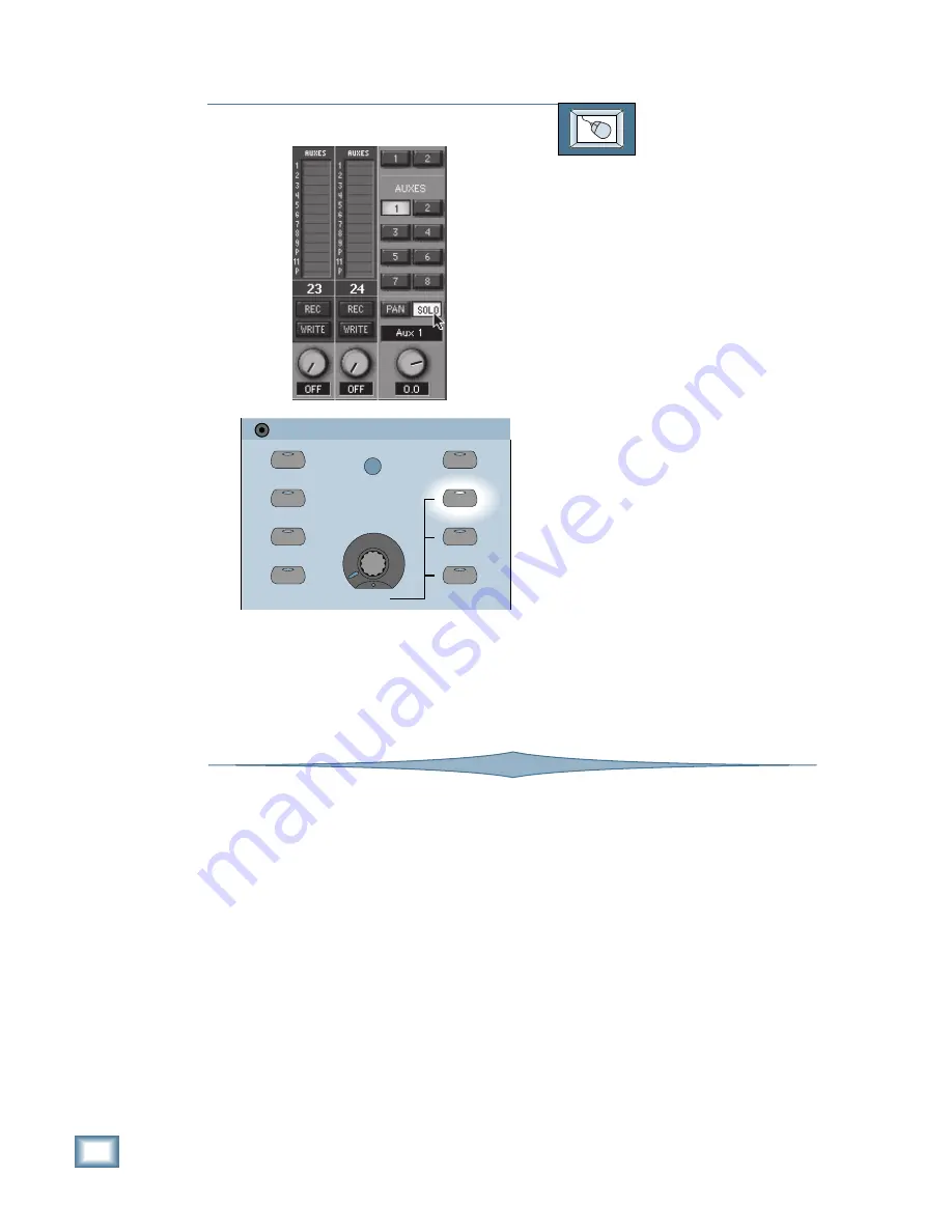
TO SOLO AN AUX SEND
From the screen:
1. Click on an aux button above the Mas-
ter V-Pot on the right side of the
screen.
2. Click on the SOLO button next to the
Master V-Pot.
3. The red LED in the SOLO button on
the console lights, and the RUDE
SOLO LIGHT in the Studio/Solo Sec-
tion begins flashing.
4.
Whatever source is selected for the con-
trol room is overridden by the solo
signal. Press SOLO LEVEL in the Stu-
dio/Solo Section to adjust the master
solo level with the LEVEL V-Pot. The
solo signal is routed to the Control
Room outputs and the Master L-R
meters indicate the signal level of all so-
loed channels and aux sends when one
or more SOLO buttons are engaged.
5. You can select a different aux bus and
solo it in the same way. Only one aux
send can be soloed at a time. You can
still solo multiple channels along with
the soloed aux send. The aux send re-
mains soloed until you either turn the
SOLO button off, or press the CLEAR
SOLO button in the Studio/Solo Sec-
tion. (The CLEAR SOLO button is not
available on the screen.)
STUDIO/SOLO
SOLO LEVEL
STUDIO LEVEL
CLEAR SOLO
TALKBACK TO
STUDIO
AFL SOLO
PFL SOLO
MIXDOWN SOLO
TALKBACK LEVEL
LEVEL
RUDE SOLO
LIGHT
Mixdown Solo
In some situations, you may want to isolate in-
dividual channels in the Main Outputs. MIXDOWN
SOLO allows you to quickly mute every channel
except for the ones that are soloed.
MIXDOWN SOLO operates a little differently
than normal soloing, because the signal at the
Main Outputs doesn’t come off the Solo bus. In-
stead, when you press the SOLO button on a
channel, all the other channels are immediately
muted. The SOLO LEVEL control has no effect on
the signal at the Main Outputs. MIXDOWN SOLO
is AFL only, and the channel faders and Master
L-R fader control the signal level.
Pressing additional channel SOLO buttons
simply unmutes those channels, allowing their
signals to pass on to the Main Outputs. The same
signal is heard in the Control Room outputs
(when L-R is selected as the source in the Control
Room Section).
Setup of Cue/Headphone Mixes for
Performers
The Digital 8•Bus has two separate phones
outputs, each of which can be independently as-
signed a different source.
Initially, you can assign the L-R outputs as
the source for Phones/Cue Mix 1 and 2 by press-
ing the CONTROL ROOM buttons in the Phones/
Cue Mix Section. This sends the signal you have
selected as a source for the Control Room to the
Phones output (in this case, the L-R bus). This
way the musicians will at least have something
to listen to right away so they can tune up and
rehearse, providing all your chosen tracks are in
record mode and auto-switching to input when
tape is not rolling.
Содержание 8-BUS Series
Страница 49: ...3 16 D i g i t a l 8 B u s Start Up ...
Страница 57: ...4 8 D i g i t a l 8 B u s Connections ...
Страница 77: ...5 20 D i g i t a l 8 B u s Preparing for a Session ...
Страница 177: ...7 20 D i g i t a l 8 B u s Automation ...
Страница 207: ...D 2 D i g i t a l 8 B u s Apogee UV22 ...
Страница 219: ...F 4 D i g i t a l 8 B u s Optional I O Cards ...
Страница 227: ...H 2 D i g i t a l 8 B u s Upgrading ...
Страница 232: ...J 3 O w n e r s M a n u a l Screen Shots Surround Sound Matrix Mackie FX Control Panel IVL Vocal Studio Control Panel ...
Страница 233: ...J 4 D i g i t a l 8 B u s Screen Shots Disk Manager File Menu Channel Menu Automation Menu Edit Menu Windows Menu ...
Страница 235: ...K 2 D i g i t a l 8 B u s ...
Страница 237: ...D i g i t a l 8 B u s ...
Страница 239: ...D i g i t a l 8 B u s ...


