2-16
D i g i t a l 8 • B u s
Digital 8•Bus Description
COLOR MONITOR Port
Connecting an optional SVGA monitor
allows for graphic display of many console
functions including secondary console layout,
equalization, compression, gating, software
library and hierarchy menus. See GUI Description
on page xx for software screen listings. (Video
pixel resolution at this port is 1024x768.)
CONSOLE DATA
Connect the supplied 25-pin D-Sub
computer cable between the CONSOLE DATA
connector on the rear panel of the console
and this connector on the Remote CPU. This
cable must be installed for the console to
communicate with the CPU.
PARALLEL Port
You can use this 25-pin D-Sub connector to
connect peripheral devices such as backup
drives and printers.
Note:
This port is not currently active, but will be
implemented in future software revisions.
SERIAL CONTROLLERS Port
This 9-pin D-Sub connector is provided for
external control of surround-sound functions
and data I/O using a joystick or trackball.
Note:
The initial version of the software may
not support the serial port. Please contact our
Tech Support department for upgrades as they
become available.
KEYBOARD Port
Connecting an optional IBM-compatible
QWERTY keyboard provides an alternative
method of accessing console functions. See
Appendix I (Shortcut Keys) for keyboard/
mouse/console equivalencies and functions.
MOUSE Port
Connecting an optional IBM-compatible
(PS/2) mouse to this port provides an
alternative method of accessing console
functions. See Appendix I for keyboard/mouse/
console equivalencies and functions.
IEC Connectors
This connector is for attaching the supplied
linecord to the Remote CPU. Make sure the
linecord is pushed all the way in to the IEC
connector. A second connector is provided for
connecting an optional color monitor to the AC
power. This second AC connector is
unswitched, and will provide power as long as
the Digital 8•Bus is plugged into an AC outlet.
POWER SUPPLY Cable
Connect this cable to the POWER SUPPLY
connector on the rear panel of the console.
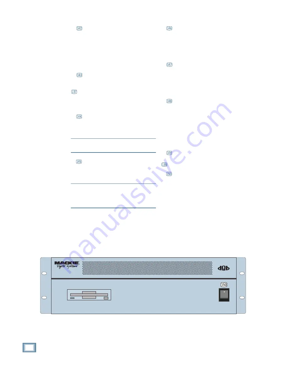
Power Switch (on the front panel)
Flip this switch to the UP position to turn on
the Digital 8•Bus. The Fat Channel Display
lights up and the console boots the Mackie
Real Time OS operating system, initializes the
internal DSPs, and lets you know when it’s
ready to start mixing.
56 INPUT
/
72 CHANNEL
MACKIE "REALTIME" OS CPU &
CONSOLE POWER SUPPLY
Содержание 8-BUS Series
Страница 49: ...3 16 D i g i t a l 8 B u s Start Up ...
Страница 57: ...4 8 D i g i t a l 8 B u s Connections ...
Страница 77: ...5 20 D i g i t a l 8 B u s Preparing for a Session ...
Страница 177: ...7 20 D i g i t a l 8 B u s Automation ...
Страница 207: ...D 2 D i g i t a l 8 B u s Apogee UV22 ...
Страница 219: ...F 4 D i g i t a l 8 B u s Optional I O Cards ...
Страница 227: ...H 2 D i g i t a l 8 B u s Upgrading ...
Страница 232: ...J 3 O w n e r s M a n u a l Screen Shots Surround Sound Matrix Mackie FX Control Panel IVL Vocal Studio Control Panel ...
Страница 233: ...J 4 D i g i t a l 8 B u s Screen Shots Disk Manager File Menu Channel Menu Automation Menu Edit Menu Windows Menu ...
Страница 235: ...K 2 D i g i t a l 8 B u s ...
Страница 237: ...D i g i t a l 8 B u s ...
Страница 239: ...D i g i t a l 8 B u s ...