4-7
O w n e r ’ s M a n u a l
Connections
Other Connections (not necessary
for operation)
You can operate virtually every function of
the Digital 8•Bus from its control surface.
However, through the use of optional input/
output devices, you may enjoy increased
productivity and ease of use.
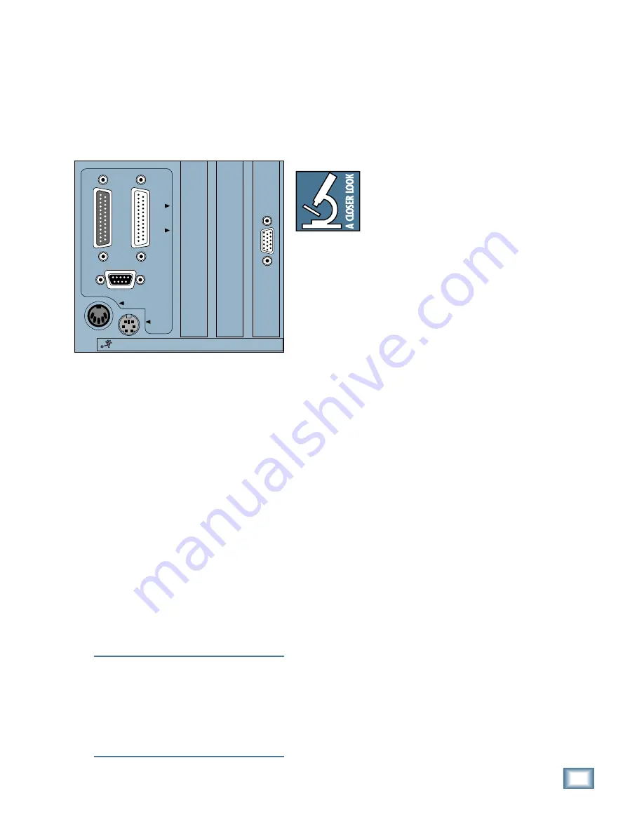
Using an SVGA Monitor
Through the use of an optional, user-supplied
SVGA monitor, it is possible to view almost all
console parameters from the built-in proprietary
Mackie Graphical User Interface (GUI).
Notice that we specify using an SVGA
monitor. That’s because SVGA provides higher
resolution than a VGA monitor. The video card
in the Digital 8•Bus produces an output
resolution of 1024 by 768 pixels with 256
colors. The highest resolution a VGA monitor
can produce is 640 by 480 pixels with 16
colors. Because of this, only part of the picture
would be reproduced on a VGA monitor,
rendering it useless.
The SVGA output uses a High Density, 15-
pin D-Sub connector. Nearly all IBM-
compatible SVGA graphic displays use the
same connector. A 17" monitor is the
recommended minimum and 21" is preferable
for reproducing the GUI with easy-to-read
clarity. When switching monitor sizes, no user
adjustments are necessary from the console.
Any SVGA monitor will show full-screen
graphic resolution.
Note:
Most SVGA monitors are multisync
(a.k.a. multiscanning) monitors, which
automatically adjust to the signal frequency of
the video display driver. If you have a fixed-
frequency monitor, be sure the monitor is
capable of reproducing 1024 by 768 pixels with
256 color resolution, at a minimum of 72Hz
refresh rate.
Using a Mouse
In conjunction with the SVGA display, an
optional PS/2 style mouse can provide greatly
increased ease of use. Use the mouse to select
all graphic symbols on the screen, including
the SMPTE display, Snapshots, Locate points,
graphic editing windows, etc. The mouse input
is an IBM-compatible, 6-pin mini-DIN, PS/2
style connector.
There are two other
standards for mouses (on a
PC): the serial mouse and
the bus mouse. A serial
mouse connects to the
computer’s serial port, which
is usually a 9-pin D-Sub connector using RS-
232 or RS-422 data transmission protocol. A
bus mouse connects to an expansion board
plugged into a computer slot, and the
connection can vary depending on the board. A
PS/2 mouse connects to a PS/2 port, which is a
6-pin mini-DIN connector on the computer, and
is often referred to as (can you guess?) the
mouse port.
Using a QWERTY Keyboard
The final input/output option is an IBM-
compatible keyboard, which can be used to
input alphanumeric names and parameters. An
extended 101-key keyboard, with a 10-key
entry pad, can be used for entering Snapshot/
Cue numbers, SMPTE times, etc. The keyboard
connector on the Remote CPU is an IBM-
compatible, 5-pin DIN-style connector.
The Ethernet Connection
Included inside the Digital 8•Bus Remote
CPU is a high-speed Ethernet card. The
Ethernet connection can be used to download
Mackie Real Time OS upgrades and effects
plug-ins, make on-line diagnoses, and make
peer-to-peer connections for transferring
sessions from one user to another. The
Ethernet connector is a standard U.S.-style,
RJ45 telco connector.
If you have a computer that has an Ethernet
connection, we recommend that you purchase
an Ethernet hub so you can have multiple
devices sharing that connection.
Connect one end of the supplied RJ45 telco
cable to the Ethernet connector on the back of
the Remote CPU, then connect the other end of
the telephone cable to an existing Ethernet
connector or Ethernet hub. Refer to Appendix
H for more information on upgrading the
operating software in your Digital 8•Bus.
CONSOLE DATA
PARALLEL
VIDEO
SERIAL
KEYBOARD
MOUSE
CONCEIVED, DESIGNED, AND MANUFACTURED BY MACKIE DESIGNS INC • WOODINVILLE • WA • USA •
THE FOLLOWING ARE TRADEMARKS OR REGISTERED TRADEMARKS OF MACKIE DESIGN INC.: "MACKIE", "D
Содержание 8-BUS Series
Страница 49: ...3 16 D i g i t a l 8 B u s Start Up ...
Страница 57: ...4 8 D i g i t a l 8 B u s Connections ...
Страница 77: ...5 20 D i g i t a l 8 B u s Preparing for a Session ...
Страница 177: ...7 20 D i g i t a l 8 B u s Automation ...
Страница 207: ...D 2 D i g i t a l 8 B u s Apogee UV22 ...
Страница 219: ...F 4 D i g i t a l 8 B u s Optional I O Cards ...
Страница 227: ...H 2 D i g i t a l 8 B u s Upgrading ...
Страница 232: ...J 3 O w n e r s M a n u a l Screen Shots Surround Sound Matrix Mackie FX Control Panel IVL Vocal Studio Control Panel ...
Страница 233: ...J 4 D i g i t a l 8 B u s Screen Shots Disk Manager File Menu Channel Menu Automation Menu Edit Menu Windows Menu ...
Страница 235: ...K 2 D i g i t a l 8 B u s ...
Страница 237: ...D i g i t a l 8 B u s ...
Страница 239: ...D i g i t a l 8 B u s ...


