6-13
O w n e r ’ s M a n u a l
Starting a New Session
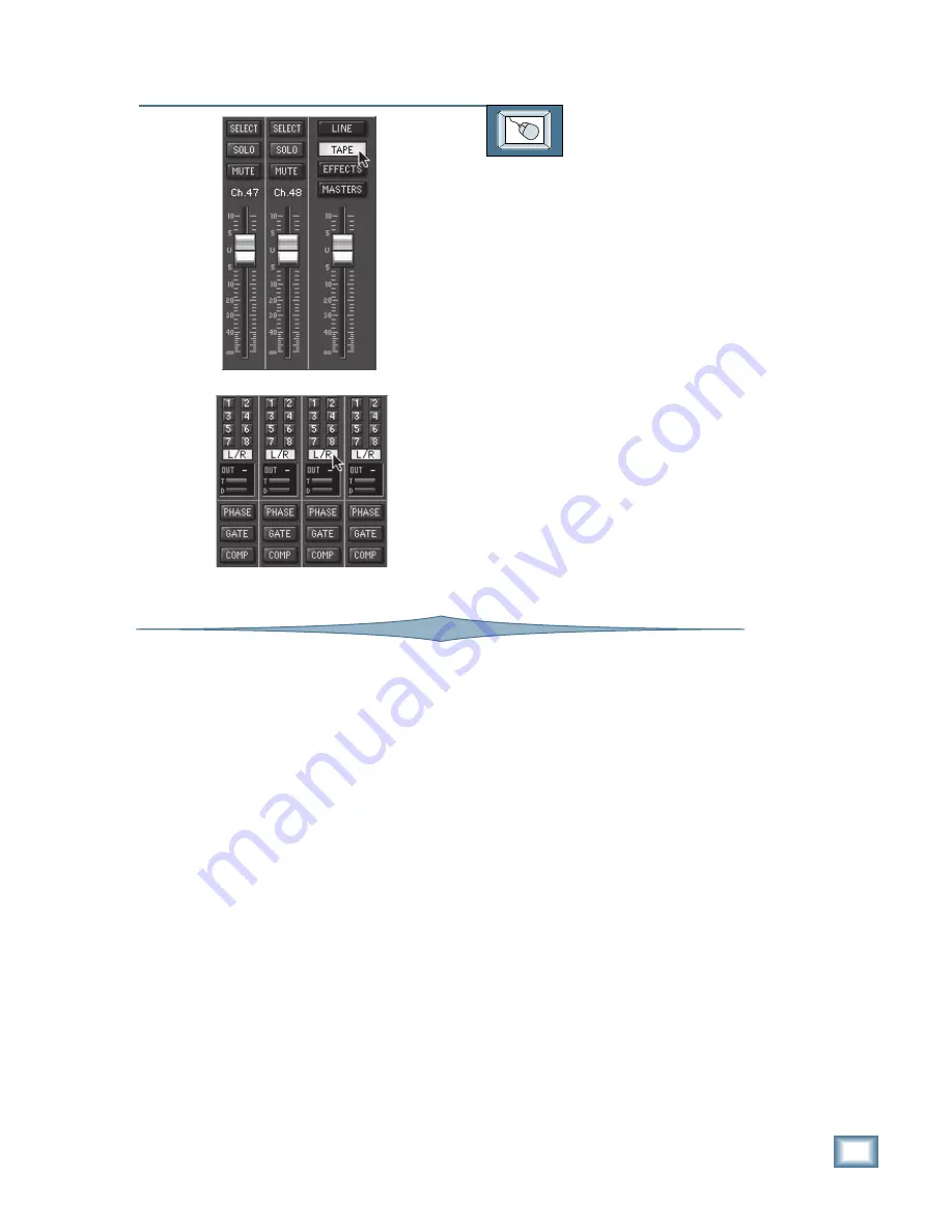
TO MONITOR IN THE CONTROL ROOM
From the screen:
1. Select Fader Bank 2 by clicking on the
TAPE button located above the Master
L-R fader.
2. If the channels aren’t already assigned
to the L-R bus, click and hold in the
L-R assignment button at the top of the
first channel strip (number 25), and
drag the mouse across all the channel
L-R buttons to assign all the channels
to the L-R bus.
3. Press the MASTER L-R button in the
Control Room Source Section (there is
no equivalent on the screen).
4. Turn the SPEAKER LEVEL V-Pot all
the way down.
5. Select the speakers you want to use for
monitoring by pressing the correspond-
ing button (MAIN or NEAR FIELD).
6. Adjust the SPEAKER LEVEL V-Pot to
a comfortable listening level.
Solo
The channel Solo function places the channel’s
signal on the stereo solo bus. This signal is post-
fader level (AFL) and post-pan by default, but it
can be changed globally to pre-fader by pressing
the SOLO PFL button in the Studio/Solo Section
(see AFL/PFL next). Whenever a SOLO button is
engaged, the stereo solo bus is routed to the Con-
trol Room Outputs, overriding whatever signal
source is selected in the Control Room Section.
The SOLO button LED lights red when it is en-
gaged and turns off when manually disabled. The
CLEAR SOLO button in the Studio/Solo Section
turns off all Solo buttons that are currently en-
gaged. A global RUDE SOLO LIGHT flashes
continually whenever any solo button is engaged
on the console.
You can solo any channel or channels at any
time without affecting the Main L-R output or any
of the Direct Outs. However, if you are using the
Main Outputs for monitoring purposes, you can
select the MIXDOWN SOLO button in the Studio/
Solo Section, and the stereo solo bus is routed to
the Main Outputs as well as to the Control Room
Outputs.
In addition, you can solo any aux send by
pressing the SOLO button in the Master V-Pot
Section whenever an aux bus is selected in the
V-Pot Select Section. Solo is useful for isolating
an individual channel to troubleshoot a problem
like distortion or buzz, to adjust EQ or dynamics
parameters, or just to listen to see if a particular
mic is open or not. When soloing more than one
source, you can listen to the blend of just part of
your mix: for example, only the sopranos, or just
the tom mics on the drums.
The solo circuits are designed not to interrupt
the recording process. The solo bus signal is
sent directly to the control room monitors with-
out affecting any of the inputs, outputs or
recording buses. The L-R Main LED ladders rep-
resent the summed signal level for the soloed
channels. When an aux send is soloed, the L-R
Main LED ladders represent the summed signal
level for the selected aux send. If a stereo aux is
soloed, the L-R Main LED ladders represent the
stereo signal of the soloed aux.
When you are mixing or monitoring with re-
verb, remember to not only solo the channel
you’d like to hear, but also the aux return carry-
ing your reverb. Otherwise, you will hear the
channel soloed dry, without its echo.
Содержание 8-BUS Series
Страница 49: ...3 16 D i g i t a l 8 B u s Start Up ...
Страница 57: ...4 8 D i g i t a l 8 B u s Connections ...
Страница 77: ...5 20 D i g i t a l 8 B u s Preparing for a Session ...
Страница 177: ...7 20 D i g i t a l 8 B u s Automation ...
Страница 207: ...D 2 D i g i t a l 8 B u s Apogee UV22 ...
Страница 219: ...F 4 D i g i t a l 8 B u s Optional I O Cards ...
Страница 227: ...H 2 D i g i t a l 8 B u s Upgrading ...
Страница 232: ...J 3 O w n e r s M a n u a l Screen Shots Surround Sound Matrix Mackie FX Control Panel IVL Vocal Studio Control Panel ...
Страница 233: ...J 4 D i g i t a l 8 B u s Screen Shots Disk Manager File Menu Channel Menu Automation Menu Edit Menu Windows Menu ...
Страница 235: ...K 2 D i g i t a l 8 B u s ...
Страница 237: ...D i g i t a l 8 B u s ...
Страница 239: ...D i g i t a l 8 B u s ...


