INDEX
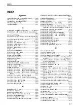
Symbols
3D points file and 3D line work file - Import.......... 7-48
3D view point settings for digging......................... 7-79
3D view point settings for driving.......................... 7-75
3D view setting contents....................................... 7-81
3D view settings....................................................7-81
A
A new layer - Create to record data..............8-50,8-53
About Komatsu HMI (About Product) menu settings...
.....................................................................7-144
Action Level Display..............................................3-10
Action when machine monitor shows warning display.
.......................................................................3-74
Air suspension seat hardness - Adjust..................3-44
Alignment - Set............................................. 7-27,7-63
Alignment centerline color - Set............................ 7-93
Alignment feature line color - Set..........................7-95
Alignment offset - Set............................................7-64
Alignment Station line color - Set..........................7-96
Angles - Set.........................................................7-116
Arm - Adjust initial speed.................................... 7-191
Arm - Adjust steady speed..................................7-192
Armrest angle - Adjust.......................................... 3-44
Armrest height - Adjust......................................... 3-43
As-Built Advanced menu.......................................7-68
As-Built Control - Set............................................ 7-69
As-Built settings.................................................... 7-66
As-built View settings............................................7-52
Authorization options display contents................7-145
Auto-Topo - Deactivate....................................... 7-134
Auto-Topo survey - Perform.................................. 8-52
Auto/Manual switch...............................................3-17
Automatic Topo survey - Set (distance based)... 7-135
Automatic Topo survey - Set (fixed time interval)7-137
Automatic Topo survey - Set (minimum horizontal dis-
tance)...........................................................7-135
Automatic Topo survey - Set (time based).......... 7-137
Avoidance Area Breach! - Action for the message......
.......................................................................3-82
Avoidance Data - Set Proximity............................ 7-50
Avoidance Data - Set shape................................. 7-50
Avoidance data settings........................................7-50
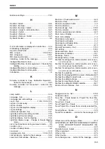
B
Background (Sky) - Set.........................................7-84
Benchmark - Compare..........................................8-28
Boom - Adjust fine control...................................7-186
Boom - Initialize fine control adjustment............. 7-189
Boom fine control adjustment............................. 7-186
Boom secondary drive switch............................... 3-16
Boundaries and break lines - Set/ Display.......... 7-102
Brightness - Adjust on Brightness adjustment screen..
..................................................................... 7-113
Brightness adjustment.........................................7-112
Bucket - Input information................................... 7-158
Bucket - Set weight............................................. 7-185
Bucket Alignment Lines - Set display..................7-110
Bucket configuration........................................... 7-150
Bucket cylinder stroke sensor wiring harness - Check
looseness of clamp and hardening of rubber...4-3
Bucket edge - Set measuring position.................. 8-26
Bucket edge - Set position.................................. 7-137
Bucket edge - Set position for navigation............. 7-63
Bucket edge accuracy - Check and adjust............8-33
Bucket edge accuracy - Check expectancy.......... 8-46
Bucket edge position.............................................8-26
Bucket edge position - Correct..............................8-29
Bucket edge position - Measure........................... 8-27
Bucket foot angle - Measure............................... 7-159
Bucket shape - Measure..................................... 7-154
Bucket shape (tilt bucket) - Measure.................. 7-165
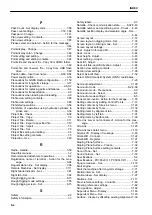
C
Cab equipment names............................................3-5
Cab front window - Close......................................3-29
Cab front window - Open...................................... 3-25
Cab front window - Open / Close.......................... 3-25
Calculating automatic calibration and writing parame-
ter value.............................................7-160,7-177
Calculating automatic calibration and writing parame-
ter value (tilt bucket).................................... 7-173
Calibration - Bucket tooth......................................8-39
Calibration - Necessary devices......................... 7-150
Calibration - Outline............................................ 7-150
Calibration - Start application after replacing bucket
tooth.............................................................7-175
Calibration - Start application after replacing conven-
tional bucket.................................................7-151
Calibration - Start application after replacing tilt buck-
et..................................................................7-162
Calibration procedure - After replacing conventional
bucket.......................................................... 7-151
Calibration procedure - After replacing tilt bucket........
.....................................................................7-162
Calibration procedure - Bucket tooth.................. 7-175
Calibration state caution lamp...............................3-13
Camera Type - Set................................................7-82
Caution lamp list................................................... 3-10
Center point of bucket - Set.................................. 7-89
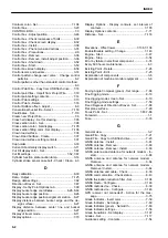
Center tab - Set.....................................................7-91
Checking contents by task detail tab...................7-119
Checks and adjustment before starting engine............
.................................................................2-8,3-40
Connection - Restart........................................... 7-143
Construction information - Set............................ 7-124
Contents of safety labels.........................................2-5
INDEX
9-1
Содержание A31001
Страница 12: ...LOCATION OF SAFETY LABELS Options are shown with marks in the figure SAFETY LABELS SAFETY 2 4...
Страница 103: ...MAINTENANCE Please read and make sure that you understand the SAFETY section before reading this section 4 1...
Страница 106: ......
Страница 107: ...SPECIFICATIONS 5 1...
Страница 110: ......
Страница 111: ...ATTACHMENTS AND OPTIONS Please read and make sure that you understand the SAFETY section before reading this section 6 1...
Страница 116: ......
Страница 117: ...SETTING 7 1...
Страница 311: ...EXECUTIONS 8 1...
Страница 376: ...PC360LCi 11 PC390LCi 11 HYDRAULIC EXCAVATOR Form No CEAM032703...

