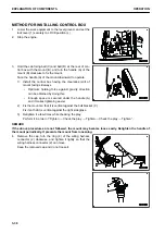
3.
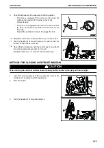
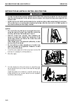
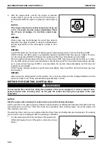
Turn the ring (4) of the wiring harness connector (2) coun-
terclockwise to disconnect the connector.
4.
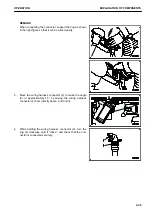
Put the cap on the disconnected connector to prevent the
dust from entering.
Control box side connector: Red cap
Chassis harness side connector: Yellow cap
REMARK
3 each of caps including spares are attached to the ma-
chine. Keep them carefully not to lose them.
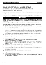
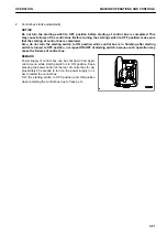
REMARK
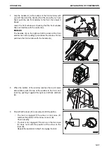
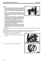
Hold the ring as shown in the figure on the right so that it
can be turned easily when disconnecting the connector.
5.
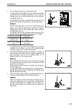
Support the control box securely not to drop. Turn the han-
dle (A) counterclockwise to loosen the mount until the ball
(D) at the rear of control box is removed from the mount.
Face the handle (A) of the mount downward to operate.
OPERATION
EXPLANATION OF COMPONENTS
3-37
Содержание A31001
Страница 12: ...LOCATION OF SAFETY LABELS Options are shown with marks in the figure SAFETY LABELS SAFETY 2 4...
Страница 103: ...MAINTENANCE Please read and make sure that you understand the SAFETY section before reading this section 4 1...
Страница 106: ......
Страница 107: ...SPECIFICATIONS 5 1...
Страница 110: ......
Страница 111: ...ATTACHMENTS AND OPTIONS Please read and make sure that you understand the SAFETY section before reading this section 6 1...
Страница 116: ......
Страница 117: ...SETTING 7 1...
Страница 311: ...EXECUTIONS 8 1...
Страница 376: ...PC360LCi 11 PC390LCi 11 HYDRAULIC EXCAVATOR Form No CEAM032703...

