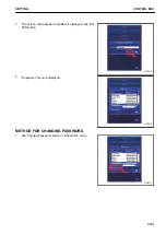
5.
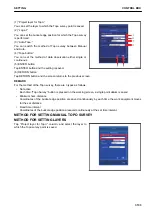
Tap “GNSS Configuration” button.
The screen changes to “GNSS Precision” screen.
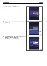
6.
For the configuration setting of the radio device, it is not
necessary to change the GNSS Precision. Tap “Next>”
button.
The screen changes to “GNSS Comms” setting screen.
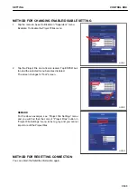
REMARK
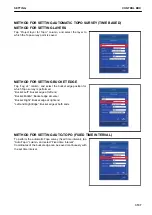
In this screen, you can set the threshold value of RMS val-
ue (error) which alerts “Low Precision” error.
You can input the value in accordance with the required
precision of the construction.
• “Max. GPS errors (roving)”: RMS threshold value used
when the machine is moving
• “Max. horz. RMS:”: Horizontal RMS threshold val-
ue
• “Max. Vert. RMS:”: Vertical RMS threshold value
• “Max. GPS errors (point measurement)”: RMS thresh-
old value used when the machine is stationary
• “Max. horz. RMS:”: Horizontal RMS threshold val-
ue
• “Max. Vert. RMS:”: Vertical RMS threshold value
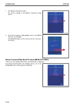
7.
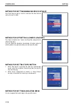
Connection information with GNSS antenna is displayed in
this screen.
If you change the information on this screen, GNSS posi-
tioning becomes disabled. Tap “Next>” button without
changing any information.
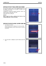
The screen changes to the radio setting screen.
$-'
$-'
$-'
SETTING
CONTROL BOX
7-147
Содержание A31001
Страница 12: ...LOCATION OF SAFETY LABELS Options are shown with marks in the figure SAFETY LABELS SAFETY 2 4...
Страница 103: ...MAINTENANCE Please read and make sure that you understand the SAFETY section before reading this section 4 1...
Страница 106: ......
Страница 107: ...SPECIFICATIONS 5 1...
Страница 110: ......
Страница 111: ...ATTACHMENTS AND OPTIONS Please read and make sure that you understand the SAFETY section before reading this section 6 1...
Страница 116: ......
Страница 117: ...SETTING 7 1...
Страница 311: ...EXECUTIONS 8 1...
Страница 376: ...PC360LCi 11 PC390LCi 11 HYDRAULIC EXCAVATOR Form No CEAM032703...

