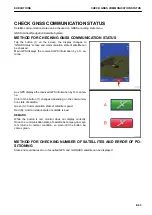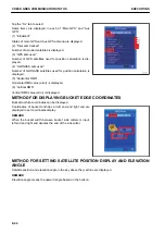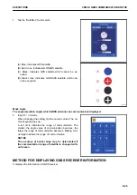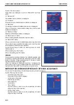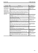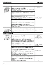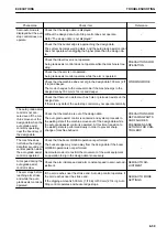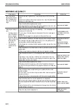
Phenomena
Check item
Reference
The facing angle
compass does not
become perpendicu-
lar to the target.
(Display of the ma-
chine is on slant
against the design
data despite of the
actual machine facing
perpendicular to the
target data.)
Check that the desired design data is selected.
Selected design data is highlighted in white. Check that the desired
one is selected.
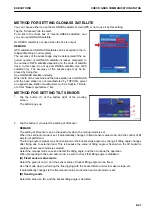
METHOD FOR SET-
TING ROUGH DIG-
GING SCREEN
(8-15)
Check that the machine is on the stable ground so that it is not shak-
en.
When the machine is operated on the unstable ground where the
machine rocks heavily, the facing angle compass may not become
perpendicular to the target due to poor response of IMU sensor sens-
ing the machine posture. However, this is not a failure.
-
Check that the bucket configuration is complied with the actual buck-
et installed.
If the bucket configuration is not correct, the display of the facing an-
gle compass is not correct, either.
Check that the screen is not 3D view.
The display of the machine may not seem to be facing perpendicular
to the target despite of the actual machine facing perpendicular to it.
However, this is not a failure.
Check that the sensor value fix mode is not set as the setting of tilt
sensor.
The display of the tilt bucket on the control box screen does not tilt
when sensor value fix mode is selected. The facing angle compass
display does not reflect the actual machine either when the actual
bucket is tilted.
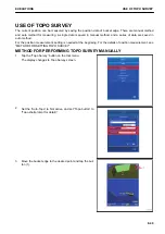
METHOD FOR SET-
TING TILT SENSOR
(8-47)
Check that there is no defect such as hole or protrusion exists on the
design data.
If any defect exists, it may not be displayed correctly.
-
Check that the machine is facing perpendicular to the target when
the upper structure swings any direction.
In this case, the color of the facing angle compass turns to gray.
METHOD FOR SET-
TING ROUGH DIG-
GING SCREEN
(8-15)
Check that the IMU adjustment is normal.
If the adjustment is necessary, perform the Adjustment Execute, and
then check again that the facing angle compass is normally dis-
played.
EXECUTIONS
TROUBLESHOOTING
8-57
Содержание A31001
Страница 12: ...LOCATION OF SAFETY LABELS Options are shown with marks in the figure SAFETY LABELS SAFETY 2 4...
Страница 103: ...MAINTENANCE Please read and make sure that you understand the SAFETY section before reading this section 4 1...
Страница 106: ......
Страница 107: ...SPECIFICATIONS 5 1...
Страница 110: ......
Страница 111: ...ATTACHMENTS AND OPTIONS Please read and make sure that you understand the SAFETY section before reading this section 6 1...
Страница 116: ......
Страница 117: ...SETTING 7 1...
Страница 311: ...EXECUTIONS 8 1...
Страница 376: ...PC360LCi 11 PC390LCi 11 HYDRAULIC EXCAVATOR Form No CEAM032703...

