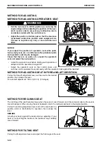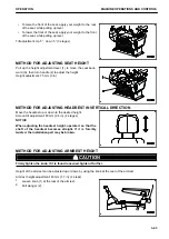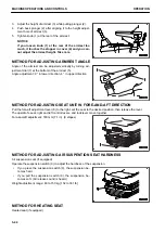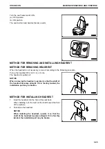
METHOD FOR REMOVING AND INSTALLING CONTROL BOX
k
k
WARNING
• For the removal and installation of control box, place the machine on a level ground, lower the work
equipment to the ground, stop the engine, check the power supply of control box is off, and then
perform the operation.
• When removing or installing the control box, always set the lock lever to LOCK position.
If the control lever or control pedal is touched by mistake when the lock lever is in FREE position, it
may cause serious personal injury or death.
NOTICE
• After operation has been done in a rain or at the humid place, dry up the control box and then store
it. If it is stored with moisture, dew condensation occurs inside and it may cause a failure or mal-
function.
Also, if the inside of the case, etc. is wet, dry up the device before storing.
• When carrying or transporting the control box, avoid the shock as much as possible by using cush-
ion. Strong shock causes a failure or malfunction.
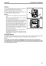
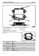
NOTICE
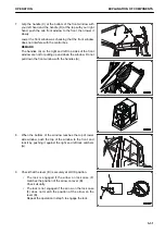
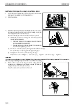
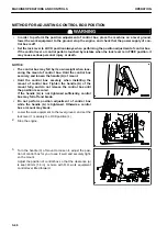
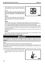
• The control box may fall by its own weight when loos-
ening the mount of control box. Hold the control box
securely, and loosen the handle (A) of mount.
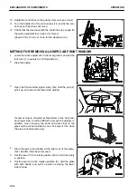
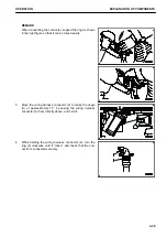
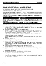
• Hold the control box securely when installing the
mount of control box. Tighten the handle (A) of the
mount fully, and do not release the control box until
the position is secured.
If the handle (A) is not tightened sufficiently, control
box may fall off and break.
• Do not perform position adjustment of control box
while the handle (A) is tightened. Otherwise, control
box or mount may break.
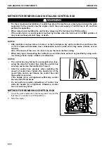
METHOD FOR REMOVING CONTROL BOX
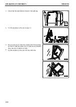
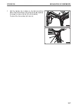
1.
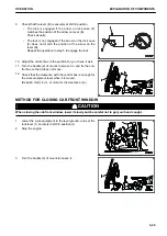
Lower the work equipment to the level ground, and set the
lock lever (1) securely to LOCK position (L).
2.
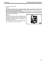
Stop the engine.
EXPLANATION OF COMPONENTS
OPERATION
3-36
Содержание A31001
Страница 12: ...LOCATION OF SAFETY LABELS Options are shown with marks in the figure SAFETY LABELS SAFETY 2 4...
Страница 103: ...MAINTENANCE Please read and make sure that you understand the SAFETY section before reading this section 4 1...
Страница 106: ......
Страница 107: ...SPECIFICATIONS 5 1...
Страница 110: ......
Страница 111: ...ATTACHMENTS AND OPTIONS Please read and make sure that you understand the SAFETY section before reading this section 6 1...
Страница 116: ......
Страница 117: ...SETTING 7 1...
Страница 311: ...EXECUTIONS 8 1...
Страница 376: ...PC360LCi 11 PC390LCi 11 HYDRAULIC EXCAVATOR Form No CEAM032703...


