


MAC III
5
Keysight 5500 SPM User’s Guide
5-24
mechanical response provided by Lock-in 1 and to see if there are any
other resonances present.
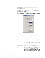
To do so, select the
KFM Servo
check box, then choose
Manual Tune
in the AC Tune window. Determining the best frequency for your
sample and tip will require some iteration. Two rules typically apply:
•
The frequency should not be an integral factor of the Lock-in 1
frequency.
•
The frequency should not be close (within 10-20 kHz) to the
Lock-in 1 frequency.
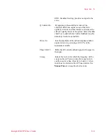
Optimize shifts the phase signal to maximize the X Component 2 (i.e.,
to maximize contrast).
The output from the servo is routed to the SP Channel and to the Drive
Offset of Lock-in 2. To map the output (which is the KFM signal),
choose
SP
in the Realtime Images window.
I Gain and P Gain are the Integral and Proportional Gains for the MAC
III internal servo loop. Set the I and P Gains to obtain the sharpest image
in the Realtime Images window.
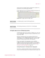
X Component 2 and Phase 2 are routed to the Aux 1 and Aux 2 outputs,
respectively, for monitoring. To view changes in the KFM signal,
choose Aux 1 in the Realtime Images window.
Advanced Software Control Options
The Advanced AC Mode property sheet gives you more signal routing
and control options than the simplified options described above. To
view the AC Mode settings, choose
Controls > Advanced > AC Mode
.
Содержание 5500
Страница 1: ...Keysight 5500 Scanning Probe Microscope User s Guide ...
Страница 2: ......
Страница 9: ...Read This First N9410 90001 Keysight 5500 SPM User s Guide ix Declaration of Conformity ...
Страница 174: ...Additional Imaging Modes 5 Keysight 5500 SPM User s Guide 5 40 Figure 7 23 Plug in Images window ...
Страница 215: ...Closed Loop Scanners 5 Keysight 5500 SPM User s Guide 5 17 Save the calibration file X Y Z calibration is now complete ...
Страница 274: ...Temperature Control 5 Keysight 5500 SPM User s Guide 5 8 Figure 13 10 7500 9500 hot sample plate wiring diagram ...
Страница 275: ...Temperature Control 5 Keysight 5500 SPM User s Guide 5 9 Figure 13 11 5500 hot MAC sample plate wiring diagram ...
Страница 276: ...Temperature Control 5 Keysight 5500 SPM User s Guide 5 10 Figure 13 12 7500 9500 hot MAC sample plate wiring diagram ...
Страница 284: ...Temperature Control 5 Keysight 5500 SPM User s Guide 5 18 Figure 13 21 5500 Peltier Cold sample plate wiring diagram ...
Страница 297: ...Thermal K 5 Keysight 5500 SPM User s Guide 5 9 Figure 14 8 Select units after calibrating the Force Constant ...
Страница 330: ...Keysight Technologies 5500 SPM User s Guide Part Number N9410 90001 Revision H Keysight Technologies 2015 ...


