Additional Imaging Modes
5
Keysight 5500 SPM User’s Guide
5-20
Interleave
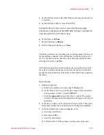
scan. The distance from the surface for the interleave scan is
determined by the Interleave Pull Away and Stop At parameters.
The topography and the MFM force gradient can be mapped
simultaneously and displayed side-by-side to highlight correlation
between the magnetic response and topography. For a typical
MFM-type cantilever with aforce constant in the range of 3 N/m and a
resonance frequency of about 75 kHz, the following setup should be
utilized, beginning with a standard topography image setup:
1
To image in MFM Mode, first follow the steps from
:
a
Insert the nose assembly into the scanner.
b
Insert an MFM probe into the nose assembly.
c
Place the scanner in the microscope base.
d
Align the laser on the cantilever.
e
Insert and align the detector.
2
Prepare the sample and place it on a sample plate.
3
Choose
Mode > AC Mode.
4
Choose
Controls > AC Mode Tune
to open the AC Tune window.
5
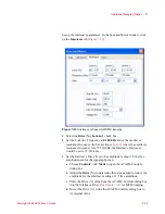
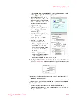
Tune the drive signal to the resonance frequency of the cantilever:
a
In the
AC Tune window, enter the Start and End frequencies (in
kHz) for the tuning sweep, typically
20-120 kHz
.
b
Set the Peak Amplitude to
3.5 to 5.0
volts.
c
Enter an Off Peak value to offset the oscillation frequency from
the cantilever’s resonance frequency. A typical value is
-0.300 kHz
. Using that setting, if the resonance frequency is
72.539 kHz, the drive frequency in the AC Tune window should
be set by the Auto Tune process to 72.239 kHz.
d
Click the
Auto Tune
button. The system will sweep through the
range of frequencies, locating the peak oscillation amplitude
within the range. This should correspond to the resonant
frequency of the cantilever. The AC signal oscillation frequency
will be set to the resonant frequency, offset by the Off Peak
parameter in the AC Tune window.
6
Bring the tip close to contact with the sample:
a
Press the
Close
switch on the HEB to raise the sample until the
tip is close to, but not touching, the sample.
b
Focus the cantilever in the video window.
c
Turn the video system focus knob toward you such that the tip
goes just out of focus (the focal plane is just below the tip now).
d
Repeat this iteratively (steps a-c) until both the tip and sample are
in focus (i.e., they are nearly touching).
Содержание 5500
Страница 1: ...Keysight 5500 Scanning Probe Microscope User s Guide ...
Страница 2: ......
Страница 9: ...Read This First N9410 90001 Keysight 5500 SPM User s Guide ix Declaration of Conformity ...
Страница 174: ...Additional Imaging Modes 5 Keysight 5500 SPM User s Guide 5 40 Figure 7 23 Plug in Images window ...
Страница 215: ...Closed Loop Scanners 5 Keysight 5500 SPM User s Guide 5 17 Save the calibration file X Y Z calibration is now complete ...
Страница 274: ...Temperature Control 5 Keysight 5500 SPM User s Guide 5 8 Figure 13 10 7500 9500 hot sample plate wiring diagram ...
Страница 275: ...Temperature Control 5 Keysight 5500 SPM User s Guide 5 9 Figure 13 11 5500 hot MAC sample plate wiring diagram ...
Страница 276: ...Temperature Control 5 Keysight 5500 SPM User s Guide 5 10 Figure 13 12 7500 9500 hot MAC sample plate wiring diagram ...
Страница 284: ...Temperature Control 5 Keysight 5500 SPM User s Guide 5 18 Figure 13 21 5500 Peltier Cold sample plate wiring diagram ...
Страница 297: ...Thermal K 5 Keysight 5500 SPM User s Guide 5 9 Figure 14 8 Select units after calibrating the Force Constant ...
Страница 330: ...Keysight Technologies 5500 SPM User s Guide Part Number N9410 90001 Revision H Keysight Technologies 2015 ...

