Preparing for Imaging
5
Keysight 5500 SPM User’s Guide
5-10
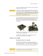
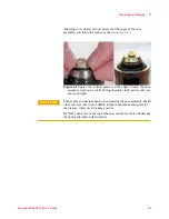
page 2). Place the body in the socket on top of the scanner, aligning its
contact pins.
Applying even, steady, vertical pressure with your fingers to seat the
body into its socket.
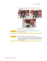
Removing the Body of the Two-Piece Nose Assembly
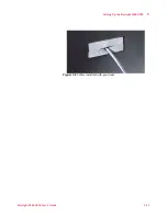
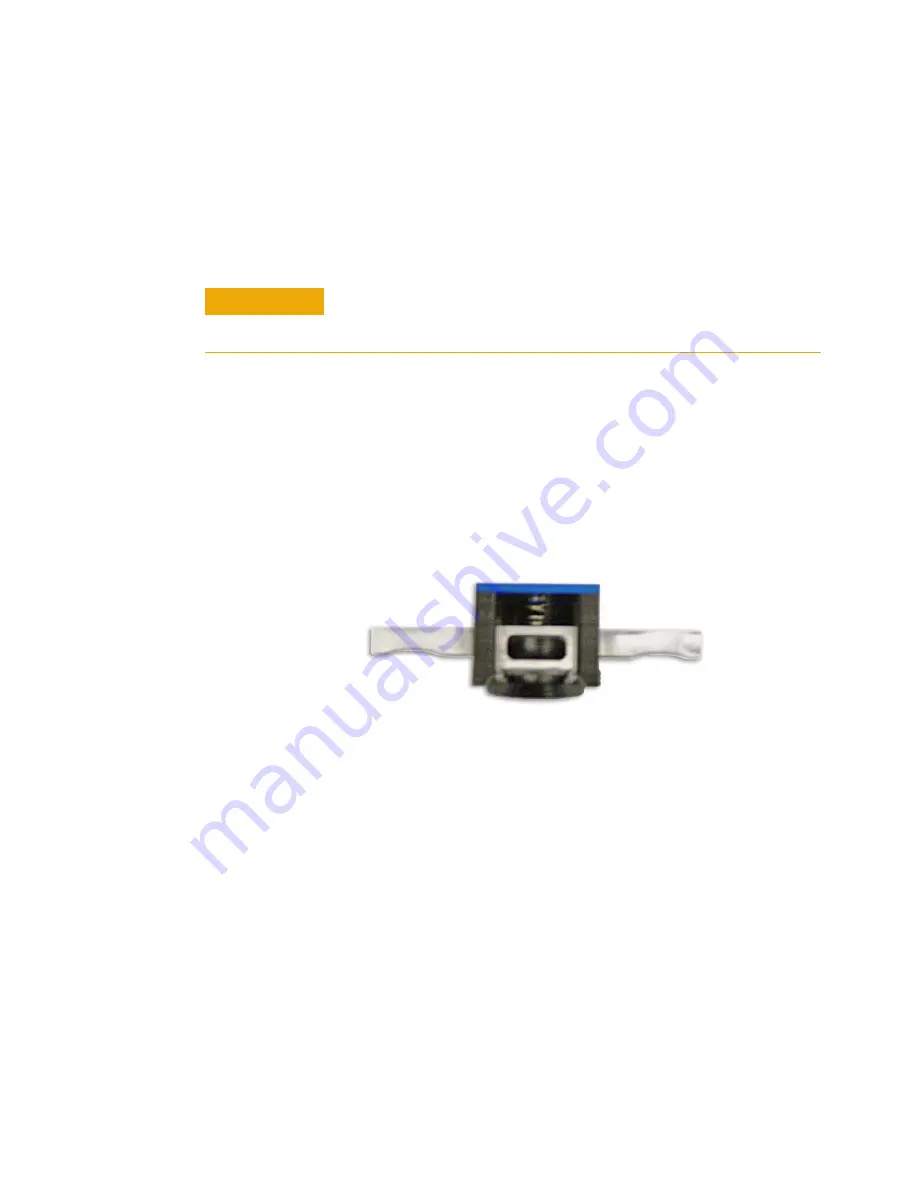
As with the one-piece nose assembly, a tool (
remove the body of the two-piece assembly from the scanner. The tool
limits damaging, lateral forces on the scanner during the removal
process. The following is the only acceptable procedure for removing
the nose assembly body:
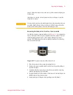
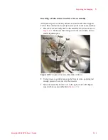
Figure 4-11
Two-piece nose assembly removal tool
1
Place the scanner in the scanner mounting fixture.
2
Remove the nose assembly disk from the body by gently pulling it
up from its edges.
3
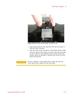
Carefully slide the removal tool onto the nose assembly, ensuring
that the opening seats on both sides.
4
Position thumb on the flat surface of the removal tool and fingers on
BOTH sides of the extraction arm.
5
Gently pull up with fingers while pushing down the thumb.
CAUTION
It is essential to push evenly and straight down when inserting the nose
assembly. Small off-axis forces will create LARGE torques about the
anchor point for the piezoes, where most breakage occurs.
Содержание 5500
Страница 1: ...Keysight 5500 Scanning Probe Microscope User s Guide ...
Страница 2: ......
Страница 9: ...Read This First N9410 90001 Keysight 5500 SPM User s Guide ix Declaration of Conformity ...
Страница 174: ...Additional Imaging Modes 5 Keysight 5500 SPM User s Guide 5 40 Figure 7 23 Plug in Images window ...
Страница 215: ...Closed Loop Scanners 5 Keysight 5500 SPM User s Guide 5 17 Save the calibration file X Y Z calibration is now complete ...
Страница 274: ...Temperature Control 5 Keysight 5500 SPM User s Guide 5 8 Figure 13 10 7500 9500 hot sample plate wiring diagram ...
Страница 275: ...Temperature Control 5 Keysight 5500 SPM User s Guide 5 9 Figure 13 11 5500 hot MAC sample plate wiring diagram ...
Страница 276: ...Temperature Control 5 Keysight 5500 SPM User s Guide 5 10 Figure 13 12 7500 9500 hot MAC sample plate wiring diagram ...
Страница 284: ...Temperature Control 5 Keysight 5500 SPM User s Guide 5 18 Figure 13 21 5500 Peltier Cold sample plate wiring diagram ...
Страница 297: ...Thermal K 5 Keysight 5500 SPM User s Guide 5 9 Figure 14 8 Select units after calibrating the Force Constant ...
Страница 330: ...Keysight Technologies 5500 SPM User s Guide Part Number N9410 90001 Revision H Keysight Technologies 2015 ...

