Additional Imaging Modes
5
Keysight 5500 SPM User’s Guide
5-19
Magnetic Force Microscopy
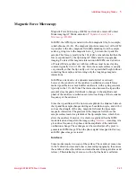
Magnetic Force Microscopy (MFM) is a derivative mode of Contact
Mode imaging, AC Mode, and also of
In MFM, the AFM tip is coated with a thin magnetic film, for example,
cobalt-chrome (Co-Cr). The magnetic (dipole) moment (
m
) of the AFM
tip couples to the stray magnetic field (
B
) emanating from the sample
surface, giving rise to the magnetic force F
m
between the tip and the
sample. This force, typically in the 10's of pN's, is much smaller than the
forces experienced by the tip during AC Mode used for topography
imaging. To detect this magnetic interaction with MFM as a derivative
of Contact Mode, cantilevers with low stiffness must be used: spring
constant typically 0.01-0.1 nN/ nm. Here, the sample surface is usually
very smooth, so that the tip can fly over it at a prescribed height without
contacting the sample, and recording only the long range magnetic
interactions.
In MFM as a derivative of a dynamic mode (lateral or vertical),
however, the sensitivity of the cantilever oscillations to small forces
make it possible to use much stiffer cantilevers, with a spring constant
typically in the 10’s of nN/nm. The interaction between the tip and the
sample's stray magnetic field leads to changes in the amplitude and
phase of the cantilever oscillations and also to a change of the resonance
frequency of the cantilever.
Since the tip oscillates with a non-zero amplitude, the distance between
the tip and the sample changes during each oscillation cycle, and with it
so does the strength of the stray magnetic field and the tip-sample
magnetic interaction: The gradient of the magnetic field above the
sample surface leads to a gradient of the tip-sample force, which then
alters the cantilever's motion. It is this force gradient that the MFM
mode detects and maps into the image, using
scanning. At a
given drive frequency, the phase and the amplitude of the cantilever
oscillations change. These changes can be recorded pixel by pixel to
generate an MFM image. When the phase signal is mapped in this way,
an MFM phase image is created.
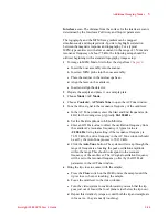
Interleave
Some modes require two scans of the surface. The cantilever scans once
in the X direction (trace and retrace), measuring topography, then raises
the cantilever above the surface and scans the same line again (trace and
retrace). This interlacing of scans on a line-by-line basis is called an
Содержание 5500
Страница 1: ...Keysight 5500 Scanning Probe Microscope User s Guide ...
Страница 2: ......
Страница 9: ...Read This First N9410 90001 Keysight 5500 SPM User s Guide ix Declaration of Conformity ...
Страница 174: ...Additional Imaging Modes 5 Keysight 5500 SPM User s Guide 5 40 Figure 7 23 Plug in Images window ...
Страница 215: ...Closed Loop Scanners 5 Keysight 5500 SPM User s Guide 5 17 Save the calibration file X Y Z calibration is now complete ...
Страница 274: ...Temperature Control 5 Keysight 5500 SPM User s Guide 5 8 Figure 13 10 7500 9500 hot sample plate wiring diagram ...
Страница 275: ...Temperature Control 5 Keysight 5500 SPM User s Guide 5 9 Figure 13 11 5500 hot MAC sample plate wiring diagram ...
Страница 276: ...Temperature Control 5 Keysight 5500 SPM User s Guide 5 10 Figure 13 12 7500 9500 hot MAC sample plate wiring diagram ...
Страница 284: ...Temperature Control 5 Keysight 5500 SPM User s Guide 5 18 Figure 13 21 5500 Peltier Cold sample plate wiring diagram ...
Страница 297: ...Thermal K 5 Keysight 5500 SPM User s Guide 5 9 Figure 14 8 Select units after calibrating the Force Constant ...
Страница 330: ...Keysight Technologies 5500 SPM User s Guide Part Number N9410 90001 Revision H Keysight Technologies 2015 ...


