


Additional Imaging Modes
5
Keysight 5500 SPM User’s Guide
5-12
14
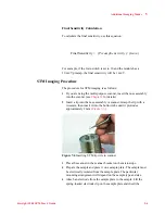
Watching the video system, bring the tip and sample very close to
contact:
a
Adjust the focus and location of the video such that the tip is in
sharp focus.
b
Lower the focal plane just slightly below the tip by turning the
Focus control toward you until the tip is slightly out of focus.
c
Now, using the
Close
switch on the HEB, raise the sample until
the sample comes nearly into focus. The tip should now be just
above the sample surface.
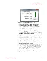
15
Click the
Approach
button in PicoView’s toolbar. The scanner will
be lowered until the Setpoint deflection voltage is reached.
16
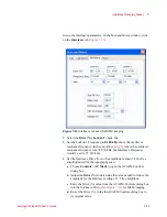
In the Servo window, make the
Setpoint
more negative until the tip
leaves contact with the sample—the indicator in the Servo window
will change from green to red. Raise the Setpoint again until the
Servo window indicator just turns green.
17
In the Scan and Motor window, click the
Up
or
Down
arrows to
begin the scan.
During the scan, the system will maintain a constant force on the tip,
and Deflection and Topography will be imaged as in Contact Mode. The
tip itself will remain at virtual ground as the bias is applied to the
sample. The current signal will be positive when the sample surface is
biased positively. The CSAFM image will show highly conductive
regions as “high” features.
The amplitude of the current signal is strongly dependent upon the
condition of the cantilever tip and sample surface, as well as the force
applied to the surface. Using known good tips, a controlled environment
and low tip force will improve imaging.
CAUTION
Raise the sample slowly and carefully to avoid collision with the
sample. Hard contact between the tip and the sample can damage either
or both.
Содержание 5500
Страница 1: ...Keysight 5500 Scanning Probe Microscope User s Guide ...
Страница 2: ......
Страница 9: ...Read This First N9410 90001 Keysight 5500 SPM User s Guide ix Declaration of Conformity ...
Страница 174: ...Additional Imaging Modes 5 Keysight 5500 SPM User s Guide 5 40 Figure 7 23 Plug in Images window ...
Страница 215: ...Closed Loop Scanners 5 Keysight 5500 SPM User s Guide 5 17 Save the calibration file X Y Z calibration is now complete ...
Страница 274: ...Temperature Control 5 Keysight 5500 SPM User s Guide 5 8 Figure 13 10 7500 9500 hot sample plate wiring diagram ...
Страница 275: ...Temperature Control 5 Keysight 5500 SPM User s Guide 5 9 Figure 13 11 5500 hot MAC sample plate wiring diagram ...
Страница 276: ...Temperature Control 5 Keysight 5500 SPM User s Guide 5 10 Figure 13 12 7500 9500 hot MAC sample plate wiring diagram ...
Страница 284: ...Temperature Control 5 Keysight 5500 SPM User s Guide 5 18 Figure 13 21 5500 Peltier Cold sample plate wiring diagram ...
Страница 297: ...Thermal K 5 Keysight 5500 SPM User s Guide 5 9 Figure 14 8 Select units after calibrating the Force Constant ...
Страница 330: ...Keysight Technologies 5500 SPM User s Guide Part Number N9410 90001 Revision H Keysight Technologies 2015 ...


