


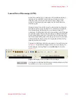


Additional Imaging Modes
5
Keysight 5500 SPM User’s Guide
5-17
For the MAC III controller these connections are made in software.
To image in Force Modulation Mode:
1
a
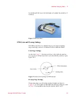
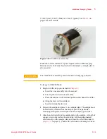
Insert the nose assembly into the scanner.
b
Insert a probe into the nose assembly.
c
Place the scanner in the microscope base.
d
Align the laser on the cantilever.
e
Insert and align the detector.
f
Prepare the sample and place it on the sample plate.
g
Configure the cable connections for MAC as described in
h
Adjust the video system to focus on the cantilever.
2
Choose
Controls > Setup > Components
, then select the
Serial
Port AC Mode Controller
check box. The system will now use the
signal from the MAC (or MAC III) controller.
3
In PicoView choose
Mode > Contact
. Or, if you are using a MAC
III controller, choose
Mode > Force Modulation
.
4
Press the
Close
switch on the HEB to raise the sample until the tip is
close to, but not touching, the sample.
5
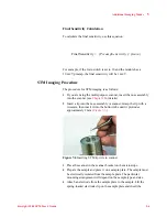
Use the video system to bring the tip and sample close to contact:
a
Bring the cantilever into sharp focus.
b
Lower the focal plane just slightly below the tip by turning the
Focus control toward you until the tip is slightly out of focus.
c
Using the
Close
switch on the HEB, raise the sample until the
sample and tip both come nearly into focus. The tip should now
be just above the sample surface.
6
Locate the area of interest on the sample by performing a scan.
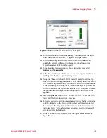
7
In PicoView’s Servo window, enter a
Setpoint
value slightly greater
than the current Deflection reading (from the HEB front panel or
PicoView’s Laser Alignment window).
8
Click the
Approach
button. The system will raise the sample until
the deflection reaches the Setpoint value.
9
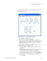
Now set up the additional AC oscillation:
a
Choose
Controls > AC Mode
to open the ACAFM Controls
window.
b
Set the Drive Mechanism to
AAC
.
c
Set the Drive % to 10 %.
d
Set the Frequency to 20-50 kHz.
Содержание 5500
Страница 1: ...Keysight 5500 Scanning Probe Microscope User s Guide ...
Страница 2: ......
Страница 9: ...Read This First N9410 90001 Keysight 5500 SPM User s Guide ix Declaration of Conformity ...
Страница 174: ...Additional Imaging Modes 5 Keysight 5500 SPM User s Guide 5 40 Figure 7 23 Plug in Images window ...
Страница 215: ...Closed Loop Scanners 5 Keysight 5500 SPM User s Guide 5 17 Save the calibration file X Y Z calibration is now complete ...
Страница 274: ...Temperature Control 5 Keysight 5500 SPM User s Guide 5 8 Figure 13 10 7500 9500 hot sample plate wiring diagram ...
Страница 275: ...Temperature Control 5 Keysight 5500 SPM User s Guide 5 9 Figure 13 11 5500 hot MAC sample plate wiring diagram ...
Страница 276: ...Temperature Control 5 Keysight 5500 SPM User s Guide 5 10 Figure 13 12 7500 9500 hot MAC sample plate wiring diagram ...
Страница 284: ...Temperature Control 5 Keysight 5500 SPM User s Guide 5 18 Figure 13 21 5500 Peltier Cold sample plate wiring diagram ...
Страница 297: ...Thermal K 5 Keysight 5500 SPM User s Guide 5 9 Figure 14 8 Select units after calibrating the Force Constant ...
Страница 330: ...Keysight Technologies 5500 SPM User s Guide Part Number N9410 90001 Revision H Keysight Technologies 2015 ...


