Contact Mode Imaging
5
Keysight 5500 SPM User’s Guide
5-5
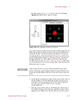
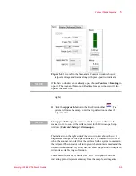
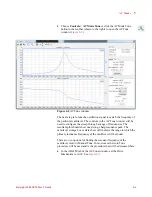
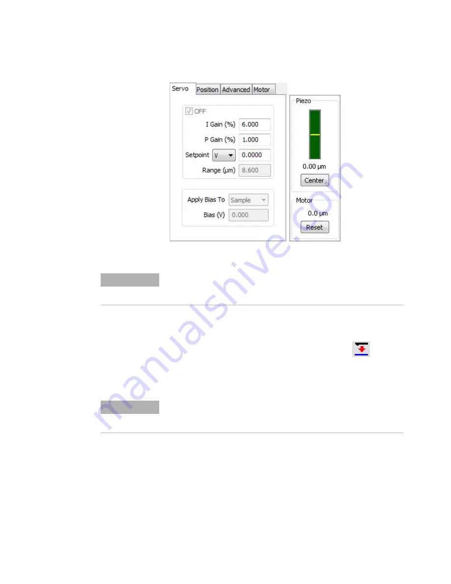
Figure 5-4
Servo tab in the Scan and Z Controls window showing
Setpoint voltage and Gains, along with piezo position indicator
(right).
13
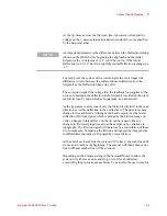
Click the
Approach
button in the PicoView toolbar
. The
system will raise the sample until the tip deflection reaches the
Setpoint value.
The indicator on the right side of the servo window shows the total
displacement range for the Z piezo actuator. The indicator will be red
when the scanner is too far from the surface for the system to maintain
the Setpoint. The indicator will turn green when contact is made and the
Setpoint is maintained. A yellow bar will show the position of the piezo
within its available range of motion.
The center of the range is defined as “zero,” with positive values
indicating piezo displacement away from the sample, and negative
NOTE
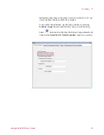
If the Servo window is not already open, choose
Controls > Imaging
to
open it. The Scan and Motor
and
Realtime Images windows will also
open at the same time.
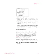
NOTE
The
Approach Range
, the distance that the system will move the
scanner to try to contact the surface, is set in the Microscope Setup
window (
Controls > Setup > Microscope
).
Содержание 5500
Страница 1: ...Keysight 5500 Scanning Probe Microscope User s Guide ...
Страница 2: ......
Страница 9: ...Read This First N9410 90001 Keysight 5500 SPM User s Guide ix Declaration of Conformity ...
Страница 174: ...Additional Imaging Modes 5 Keysight 5500 SPM User s Guide 5 40 Figure 7 23 Plug in Images window ...
Страница 215: ...Closed Loop Scanners 5 Keysight 5500 SPM User s Guide 5 17 Save the calibration file X Y Z calibration is now complete ...
Страница 274: ...Temperature Control 5 Keysight 5500 SPM User s Guide 5 8 Figure 13 10 7500 9500 hot sample plate wiring diagram ...
Страница 275: ...Temperature Control 5 Keysight 5500 SPM User s Guide 5 9 Figure 13 11 5500 hot MAC sample plate wiring diagram ...
Страница 276: ...Temperature Control 5 Keysight 5500 SPM User s Guide 5 10 Figure 13 12 7500 9500 hot MAC sample plate wiring diagram ...
Страница 284: ...Temperature Control 5 Keysight 5500 SPM User s Guide 5 18 Figure 13 21 5500 Peltier Cold sample plate wiring diagram ...
Страница 297: ...Thermal K 5 Keysight 5500 SPM User s Guide 5 9 Figure 14 8 Select units after calibrating the Force Constant ...
Страница 330: ...Keysight Technologies 5500 SPM User s Guide Part Number N9410 90001 Revision H Keysight Technologies 2015 ...


