


MAC III
5
Keysight 5500 SPM User’s Guide
5-23
frequency at which the tip oscillation is
maximized (i.e., the resonant frequency).
Gain
Multiplies the output of the lock-in by the
selected factor. Use a larger multiplier to
improve the signal-to-noise ratio for a small
signal. Ensure that the gain will not result in an
amplitude exceeding 10 V, beyond which the
signal will be clipped. The default value is x1
(the amplitude times 1).
Zero Phase
Sets the phase at the current frequency to zero,
making it easier to interpret phase changes from
the current value.
Q Control On
By applying a phase-shifted version of the
cantilever deflection signal on top of the drive
signal, Q control can either increase or decrease
the effective quality factor of the system. Select
this
On
check box to enable the Q Control
feedback loop. By default, Q Control is turned
Off.
Drive (%)
Sets the amplitude of the Q Control phase-shifted
signal, stated as a percentage (0-100 %) of the
maximum available.
Optimize
Sets the optimal Q-Control Phase Shift and
Drive.
The KFM tab shows the parameters for Lock-in 2.
Drive
,
Frequency,
Bandwidth
(Lock-in 2 and 3) and
Gain
(Lock-in 2 and 3) settings have
the same functions as described for Lock-in 1 in
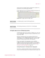
As mentioned, Lock-in 2 is used as the source for the AC tip bias. You
will typically need to sweep the frequency of Lock-in 2 to ensure that
the electrical response of the cantilever does not interfere with the
Содержание 5500
Страница 1: ...Keysight 5500 Scanning Probe Microscope User s Guide ...
Страница 2: ......
Страница 9: ...Read This First N9410 90001 Keysight 5500 SPM User s Guide ix Declaration of Conformity ...
Страница 174: ...Additional Imaging Modes 5 Keysight 5500 SPM User s Guide 5 40 Figure 7 23 Plug in Images window ...
Страница 215: ...Closed Loop Scanners 5 Keysight 5500 SPM User s Guide 5 17 Save the calibration file X Y Z calibration is now complete ...
Страница 274: ...Temperature Control 5 Keysight 5500 SPM User s Guide 5 8 Figure 13 10 7500 9500 hot sample plate wiring diagram ...
Страница 275: ...Temperature Control 5 Keysight 5500 SPM User s Guide 5 9 Figure 13 11 5500 hot MAC sample plate wiring diagram ...
Страница 276: ...Temperature Control 5 Keysight 5500 SPM User s Guide 5 10 Figure 13 12 7500 9500 hot MAC sample plate wiring diagram ...
Страница 284: ...Temperature Control 5 Keysight 5500 SPM User s Guide 5 18 Figure 13 21 5500 Peltier Cold sample plate wiring diagram ...
Страница 297: ...Thermal K 5 Keysight 5500 SPM User s Guide 5 9 Figure 14 8 Select units after calibrating the Force Constant ...
Страница 330: ...Keysight Technologies 5500 SPM User s Guide Part Number N9410 90001 Revision H Keysight Technologies 2015 ...


