


Contact Mode Imaging
5
Keysight 5500 SPM User’s Guide
5-2
Setting Up for Contact Mode Imaging
Contact Mode imaging can be completed with any of the multi-purpose
scanners, using most any AFM probe and nose assembly. Contact Mode
tips, however, are designed specifically for this application, with lower
resonance frequency, softer cantilevers.
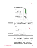
Constant Force Mode
In Constant Force Mode, a feedback loop between the Head Electronics
Box (HEB) and the controller maintains a constant deflection of the tip
based on the specified Setpoint voltage. The error signal, which is the
difference, measured in volts by the photodetector, between the Setpoint
and actual cantilever deflection, is read as the Deflection.
To begin imaging, follow the steps detailed in
1
Insert the nose assembly into the scanner.
2
Insert a probe into the nose assembly.
3
Place the scanner in the microscope and connect the cables.
4
Align the laser on the cantilever.
5
Insert and align the detector.
6
Prepare the sample and place it on the sample plate.
Then:
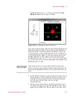
7
In the PicoView software choose
Mode > Contact
.
8
Choose
Controls > Camera View
to open the Camera View video
window.
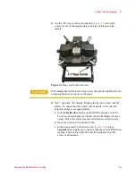
9
Use the
Close
switch on the HEB to raise the sample until the tip is
close to, but not touching, the sample.
10
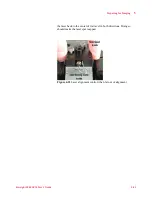
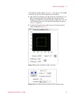
Viewing the video window, bring the tip and sample very close to
contact:
c
Adjust the focus and x-y alignment of the video system such that
the tip is in sharp focus (
).
Содержание 5500
Страница 1: ...Keysight 5500 Scanning Probe Microscope User s Guide ...
Страница 2: ......
Страница 9: ...Read This First N9410 90001 Keysight 5500 SPM User s Guide ix Declaration of Conformity ...
Страница 174: ...Additional Imaging Modes 5 Keysight 5500 SPM User s Guide 5 40 Figure 7 23 Plug in Images window ...
Страница 215: ...Closed Loop Scanners 5 Keysight 5500 SPM User s Guide 5 17 Save the calibration file X Y Z calibration is now complete ...
Страница 274: ...Temperature Control 5 Keysight 5500 SPM User s Guide 5 8 Figure 13 10 7500 9500 hot sample plate wiring diagram ...
Страница 275: ...Temperature Control 5 Keysight 5500 SPM User s Guide 5 9 Figure 13 11 5500 hot MAC sample plate wiring diagram ...
Страница 276: ...Temperature Control 5 Keysight 5500 SPM User s Guide 5 10 Figure 13 12 7500 9500 hot MAC sample plate wiring diagram ...
Страница 284: ...Temperature Control 5 Keysight 5500 SPM User s Guide 5 18 Figure 13 21 5500 Peltier Cold sample plate wiring diagram ...
Страница 297: ...Thermal K 5 Keysight 5500 SPM User s Guide 5 9 Figure 14 8 Select units after calibrating the Force Constant ...
Страница 330: ...Keysight Technologies 5500 SPM User s Guide Part Number N9410 90001 Revision H Keysight Technologies 2015 ...


