−
115
−
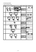
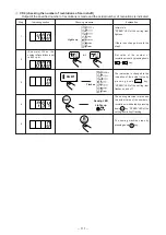
[Explanation of the indication]
Indication
1
Indication of key code from operation panel
Two digits of the number corresponding to the key will be shown when operation panel is pressed.
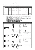
Codes corresponding to each key are as shown in the following table.
Indication
2
Value of variable resistor
Value of the variable resistor located on the left side of operation panel is shown.
The value indicated is from 0 to 255. (However, in some cases, “0” or “255” will not be shown because of
the unstable work of the variable resistor.)
Indication
3
Switch input
Pedal, temporary stop switch, etc. are shown.
The indication will be as follows.
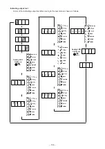
※
Normally, when the
“1” switch is ON, “0”
is shown.
For the temporary
stop switch and the
feeding frame 1
switch, when the “0”
switch is ON, “1” is
shown.
Code
25
26
27
28
29
30
31
32
33
34
*
*
*
*
*
*
*
*
Feeding frame 1 (right)
Feeding frame 2 (left)
Feeding frame 3
Feeding frame 4
Start switch
Air switch
Temporary stop
Thread breakage detection
Switch name
Bobbin thread
winder
Threading
Clear
Advance
Retract
Return-to-origin
Test
Code
01
02
03
04
05
06
07
08
Switch name
0 key
1 key
2 key
3 key
4 key
5 key
6 key
7 key
8 key
9 key
Code
10
11
12
13
14
15
16
17
18
19
Switch name
Pattern No.
X scale
Y scale
Bobbin thread set
Bobbin thread
replacement
Code
20
21
22
23
24
Switch name
Input selection
Code
F1
F2
Jump
Point sewing
Linear sewing
Thread trimming
Read-out
Write-in
Switch name
Data deletion
Speed change
Curve point
End point
Execution/End
Code
35
36
37
38
39


