


−
25
−
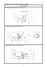
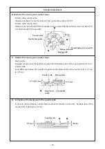
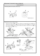
1) Installing position of the tension release notch
2) Position of the tension release stopper
When tension release arm
7
is moved in the direction A in the state that the cam installing link is
separated from thread trimmer cam
6
(in the state that tension relase arm
7
comes in contact with
tension release link
8
), adjust the clearance between the periphery of thread trimmer cam
6
and
tension release arm pin
5
to 1.2 mm.
3) Floating amount of the thread tension disk
2
3
4
1
2
3
4
5
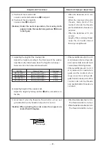
(6) Adjustment of the tension release components
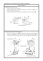
Standard Adjustment
(Thread
tension disk)
Return spring
Widen
(Tension
release link)
Narrow
Floating
amount A
Thread trimmer cam
1
2
To come in
contact with
each other
5
1.2 mm
7
6
8
B
2
3
4
1
Close contact
A
b
e