


−
19
−
0.3 mm
0.3 mm
1
2
3
4
5
6
A
B
1
A
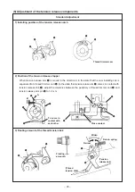
Standard Adjustment
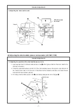
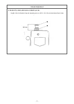
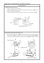
3)
Position of the thread trimmer shaft
Make sure that the rear end of thread trimmer shaft
4
aligns with the processed face
A
of the sewing
machine arm in the state that tension release pin
2
of tension release arm
1
is separated from
tension release notch
3
(thread trimmer stopper support comes in contact with the section
B
of the
sewing machine arm stopper.).
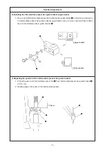
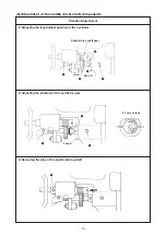
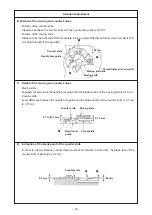
4)
Position of the cam installing link stopper
1. Clearances between notch
A
of the cam installing link and the cam installing link are 0.3 mm each
in the state that the thread trimmer is separated “thread trimmer stopper support comes in contact
with the section
B
of the sewing machine arm stopper” (see the previous item 3).).