


−
8
−
Adjustment Procedures
Results of Improper Adjustment
Adjustment Procedures
Results of Improper Adjustment
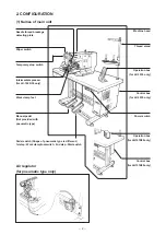
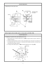
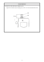
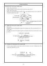
1) Remove sensor cover
2
.
2) Fit the sensor installing base to face A.
Tighten setscrew
1
so that slit plate
3
passes the center of
the sensor without interfering with each other and put the sensor
cover.
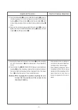
™
If the position of the intermediate
presser cam in the direction of
rotation is not proper, stitch
skipping, needle breakage, etc.
will occur.
™
I f t h e c l e a r a n c e p r o v i d e d
b e t w e e n t h e i n t e r m e d i a t e
presser driving arm and the
machine arm boss is too small,
they come in contact with each
other during sewing, and noise
may occur.
If the clearance is too large,
pressure of the intermediate
presser is increased. As a result,
maloperation or trouble will be
caused.
™
If the main shaft sensor is not
properly installed, the sensor
may be damaged or error may
ocur.
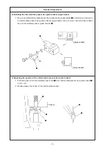
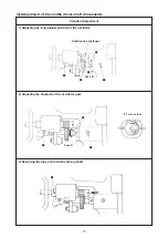
1) Turn the main shaft engraved dot A of the main shaft comes
just above.
2) Insert a thickness gauge of 0.5 mm between section C of the
intermediate presser driving arm and section D of machine
arm boss and make a state that section C of the intermediate
presser driving arm, thickness gauge and section D of the
machine arm boss come in close contact altogether.
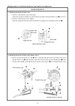
3) Turn intermediate presser cam
1
while lightly pressing it to
intermediate poresser roller
3
so that engraved dot A of
intermediate presser cam
1
is aligned with engraved dot B of
the main shaftin the direction of rotation. Then tighten two
setscrews E.
4) Closely fit intermediate presser cam stopper
2
to intermediate
presser cam
1
and tighten two setscrews F.