−
17
−
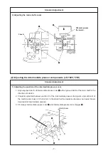
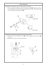
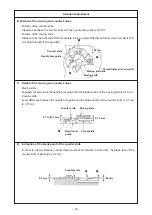
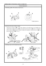
1) Adjusting the thread trimmer cam
1. Position of the direction of the main shaft :
Adjust the clearance between the main shaft thrust collar and thread trimmer cam
3
to 0.5 mm.
2. Position of the direction of the rotation :
Align the engraved point of the main shaft with the engraved line of thread trimmer cam
3
.
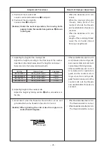
2) Adjusting the thread trimmer link stopper screw
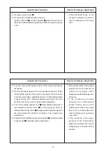
1. Make sure that thread trimmer roller
2
has a clearance against the both end faces of the slit of
thread trimmer cam
6
and smoothly enters the slt when pushing cam installing link
1
in the
direction of arrow (
b
) in the approach run section (in the range of
A
) of the thread trimmer cam.
1
2
3
1
2
3
4
5
6
A
3
(Clearance0.5 mm)
2
4
B
(5) Adjustment of the thread trimmer mechanism components
Standard Adjustment
Engraved line
Main shaft
Engraved point
Main shaft thrust collar
Main shaft
Thread trimmer cam
Thread trimmer cam
Half rotation after contacting
b

