


−
34
−
Adjustment Procedures
Results of Improper Adjustment
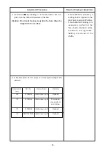
™
The load of the feed will become
large, causing the failure of the
feed.
™
N o i s e o f f e e d i n g c l o t h i s
increased at the time of sewing
unless the feed plate support
plate is pressed in the
a
direction.
™
The load of the feed will become
large, causing the failure of the
feed or noise.
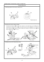
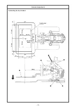
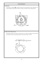
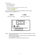
1) Loosen two Y feed arm setscrews
1
.
2) Push Y feed shaft
2
in the direction of arrow
f
.
3) Loosen three setscrews
3
in the feed plate support plate, and
lightly press the feed plate support plate in the
a
direction.
Moving Y feed arm
4
in the
ba
direction making Y feed shaft
2
as a guide, fix feed plate support plate
5
to the position
where there is no torque.
4) Align Y feed shaft
2
with end face A of Y feed arm
4
and
securely tighten Y feed arm setscrews
1
.
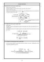
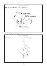
1) Insert feed plate
1
into Y feed support shaft
2
.
2) Enter thrust collar
3
to Y feed support shaft
2
, push feed
plate
1
to feed plate support plate
4
, and remove the thrust.
Then tighten two setscrews
5
.
(Caution) When tightening setscrews
5
, move feed plate
1
in the direction of arrow and tighten the setscrews
so that the position of the setscrews becomes as
shown in Fig. 1.
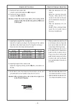
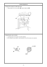
3) Place square block
6
in the slot portion of feed plate
1
and
insert X feed support shaft
7
into X feed arm
8
.
(Caution) 1. Adjust the flat section to the position of the
screw.
2. The square block
6
is a selective part.
Select a square block which is rather tight
against the slot portion of feed plate
1
.
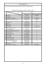
B1414232000 ...... Loose
B141423200A ..... Medium
B141423200B ..... Tight
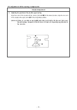
4) Lightly push the flange section of X feed support shaft
7
to
feed plate
1
in the state that a spacer of 0.25 mm is inserted
between feed plate
1
and X slide plate
!0
, and tighten setscrew
9
.