−
107
−
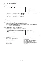
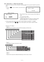
2) How to check each test program No.
1
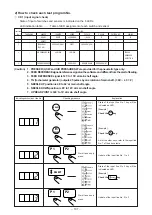
CP-1 (input signal check)
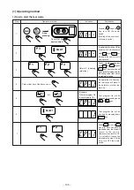
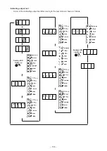
State of input of switches and sensors is indicated on the 8 LEDs.
LED indication table ......... Table of LED assignment of each switch and sensor
Input line
Kind of LED
No.
THREADING
WINDER
COUNTER
SPEED
Y SCALE
X SCALE
PATTERN NO.
SEWING
1
–
READY
RESET
+/ FORWARD
–/ BACK
P1
P2
P3
2
–
SELECT
–
–
–
–
–
–
3
–
PRESSER (R) SW
START
PRESSER (L) SW
–
–
–
4
–
AIR PRESSURE SW
X ORIGIN
Y ORIGIN
–
–
–
5
–
FEED REFERENCE
TG
NEEDLE UP
NEEDLE DOWN
UP DEAD POINT
–
–
(Caution)
1. PRESSER (L) SW and AIR PRESSURE SW are provided for the pneumatic type only.
2. FEED REFERENCE signal is reference signal on the software and different from the start of feeding.
3. FEED REFERENCE signal is 125˚ to 155˚ at main shaft angle.
4. TG (tachometer generator) outputs 45 pulses by one rotation of main shaft. ( 360˚
÷
45 = 8˚)
5. NEEDLE UP position is 46˚ to 62˚ at main shaft angle.
6. NEEDLE DOWN position is 80˚ to 123˚ at main shaft angle.
7. UP DEAD POINT is 340˚ to 10˚ at main shaft angle.
TEMPORARY
STOP SW
THREAD
BREAKAGE
DETECTION
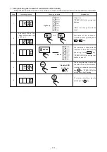
Indicating section (input line No.)
Checking measure
Explanation
READY
RESET
R
P 1
P 2
SELECT
Simultaneously
press.
P 1
P 2
Simultaneously
press.
Update of the input line No. 2 to 3
Check the
SELECT
key.
Update of the input line No. 1 to 2
As for the other keys, refer to the input line
No. 1 of the above table.
State of the input line No. 1 key will be
indicated on LED.
Check the
READY
key.
Check the
RESET
R
key.
State of the input line No. 2 key will be
indicated on LED.
[Example]
[Example]
[Example]


