−
26
−
Adjustment Procedures
Results of Improper Adjustment
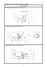
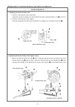
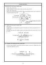
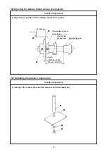
1) Loosen two setscrews
1
in the tension release notch, and
move tension release notch
2
to the center of the long slit.
Then securely tighten two setscrews
1
to fix it.
2) After the adjustment, pushing cam installing link
3
in the
direction of arrow (
f
) by hand, rotate the main shaft in the
normal direction (
a
), and ride tension release pin
4
on tension
release notch
2
. After that, let go of the hand, and make the
main shaft in the normal direction.
Make sure that tension release pin
4
separates from tension
release notch
2
at the position where the thread take-up lever
has passed the upper dead point.
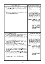
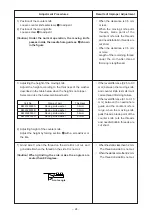
1) Remove tension release return spring
1
.
2) Loosen two setscrews
2
. If the tension release stopper with
tension release adjusting arm closely contacted is pushed in
the direction of arrow (
e
), the learance will be narrowed. If
pushing it in the direction of arrow (
a
), the clearance will be
widened.
3) Adjust the clearance to 1.2 mm, tighten setscrews
2
, and hook
tension release return spring
1
.
4) After the adjustment, tension release arm
7
slightly comes
down in the direction of B by the tare.
Move tension release arm
7
in the direction of A or B and
make sure that there is a play.
(Caution) After adjusting the position of the tension release
stopper, check to be sure of the thread tension disk
floating amount described in the next item 3).
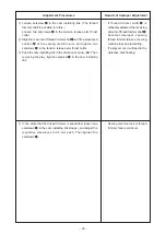
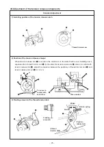
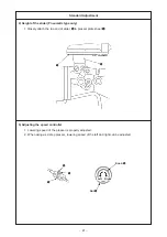
1) Remove the arm cover, and make sure that tension release
pin
3
rides on tension release notch
4
.
2) If the pin does not ride on the notch, push cam installing link
5
by hand in the
e
direction, and rotate the main shaft in the
normal direction to make the state shown in the figure.
3) Under the state shown in the figure, loosen setscrew
2
in the
tension release adjusting arm. Floating amount of the thread
tension disk will vary by moving tension release adjusting arm
1
to the right or left.
Disk floating amount A :
S type : 0.6 to 0.8 mm
H type : 0.8 to 1.0 mm
(Caution) If disk floating amount is too small, the length of
remaining thread after thread trimming will vary. If
the disk floating amount is excessive, disk closing
failure after the release of disk floating will occur.
™
If the clearance is excessive,
when adjusting the disk floating
amount to rather excessive, the
disk cannot close completely
when the disk floating is relesed,
causing stitch failure.
™
If the clearance is too small,
malfunction of the thread trimmer
shaft ( a load is produced) will
occur, causing thread trimming
failure or machine lock.
™
Length of remaining needle
thread after thread trimming will
be shortened.
Also, the length will vary.
™
Needle thread may slip off from
the needle at the sewing start.
™
If the disk floating amount is too
samll, the length of remaining
needle thread after thread
trimming will be shortened or the
length will vary to a great extent.
™
If the disk floating amount is
excessive, the disk can not close
completely after the release of
disk floating, causing stitch
failure.

