−
148
−
20. MAINTENANCE AND INSPECTION
(1) Replacing the printed circuit boards
Types of printed circuit boards
1
MAIN circuit board (Control box)
2
SERVO circuit board (Control box)
3
PMDC circuit board (Control box) (For LK-1930 only)
4
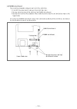
POWER circuit board (Control box)
1) MAIN circuit board
Acts as the brain of this machine and outputs the control signals to control the floppy disk driver unit, and
to follow the program to operate the sewing machine head and the operation panel.
1
Turn OFF the power switch, and open the control box cover.
2
Remove all connectors (J10 to J24) from the MAIN circuit board.
3
Remove four fixing screws from the circuit board and replace the circuit board with a new one.
4
Install the new MAIN circuit board by reversing the above disassembly order. Connect the connectors
matching the numbers indicated on the circuit board and the numbers attached to the connectors.
(Caution) The battery for the data back-up is mounted on the MAIN circuit board. Be sure not to
place the circuit board on metal plate or the like. Never wrap the MAIN circuit board with
a sheet of aluminum foil.
2) SERVO circuit board
The SERVO circuit board receives the control signals from the MAIN circuit board, and actuates the servo
motor for main shaft of the sewing machine.
1
Turn OFF the power switch, and open the control box cover.
2
Remove all connectors (J1 to J5) from the SERVO circuit board.
3
Remove four fixing screws (fixed from outside of the control box) from radiating plate, and replace
with a new circuit board.
4
Install the new circuit board by reversing the above disassembly order.
3) PMDC circuit board (For LK-1930 only)
The PMDC circuit board receives the stepping motor driving signals from the MAIN circuit board, and acts
to drive the X and Y stepping motors.
1
Turn OFF the power switch,and open the control box cover.
2
Remove all connectors (J60 to J62) from the PMDC circuit board.
3
Remove four fixing screws on the radiating plate, and remove four studs attaching the MAIN circuit
board. Then replace with a new circuit board.
4
Install the new circuit board by reversing the above disassembly order. Install the circuit board so that
the connector J60 is positioned on the left side.
(Caution) Be sure to securely tighten the fixing screws. The tightening torque has been specified
to 14 kg at the time of delivery.


