www.jps.com.tw
70
13.3 Timer Group
13.3.1 Timer Group Parameters
The drive has embedded two timer module (Timer A, Timer B); below section will describe the
function and application of these two timer.
z
Pr.249
Æ
Type of Timer A
This parameter can set the operation type of Timer A.
Value
Description
0
Timer A Delay Off Mode
1
Timer A Delay On Mode
2
Timer A Auto On/Off Mode
z
Pr.250
Æ
T1 time of Timer A.
z
Pr.251
Æ
T2 time of Timer A.
z
Pr.252
Æ
Type of Timer B.
This parameter can set the operation type of Timer B.
Value
Description
0
Timer B Delay Off Mode
1
Timer B Delay On Mode
2
Timer B Auto On/Off Mode
z
Pr.253
Æ
T1 time of Timer B.
z
Pr.254
Æ
T2 time of Timer B.
13.3.2 Timer Group Digital-Input
z
DIx _ Select
Æ
60, TIMER-A "TRIG/START" input
z
DIx _ Select
Æ
61, TIMER-B "TRIG/START" input
13.3.3 Timer Group Digital-Output
z
DOx _ Select
Æ
104, Timer A output “Q”
z
DOx _ Select
Æ
105, Timer A output “/Q”
z
DOx _ Select
Æ
106, Timer B output “Q”
z
DOx _ Select
Æ
107, Timer B output “/Q”
Description of the usage:
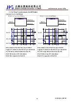
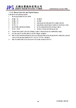
Below section will description the way to set and start the timer. All the two timers are individual and
have there own parameter group for setting.
1.
Select the function type of timer; for Timer A use Pr.249, for Timer B use Pr.252.
2.
Define the action time of the timer; for Timer A use Pr.250 and Pr.251, for Timer B use Pr.253 and Pr.254.
3.
Define a DI to be the Enable input of timer.
4.
Define a DO to be the output of timer.
Содержание IRIS-IMSV
Страница 1: ...IRIS IMSV DRIVER USER MANUAL Version V5 03 ...
Страница 95: ...16 CE Certificate 16 1 EMC Certificate www jps com tw 94 ...
Страница 96: ...16 2 LVD Certificate www jps com tw 95 ...

