
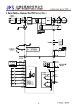
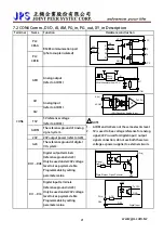
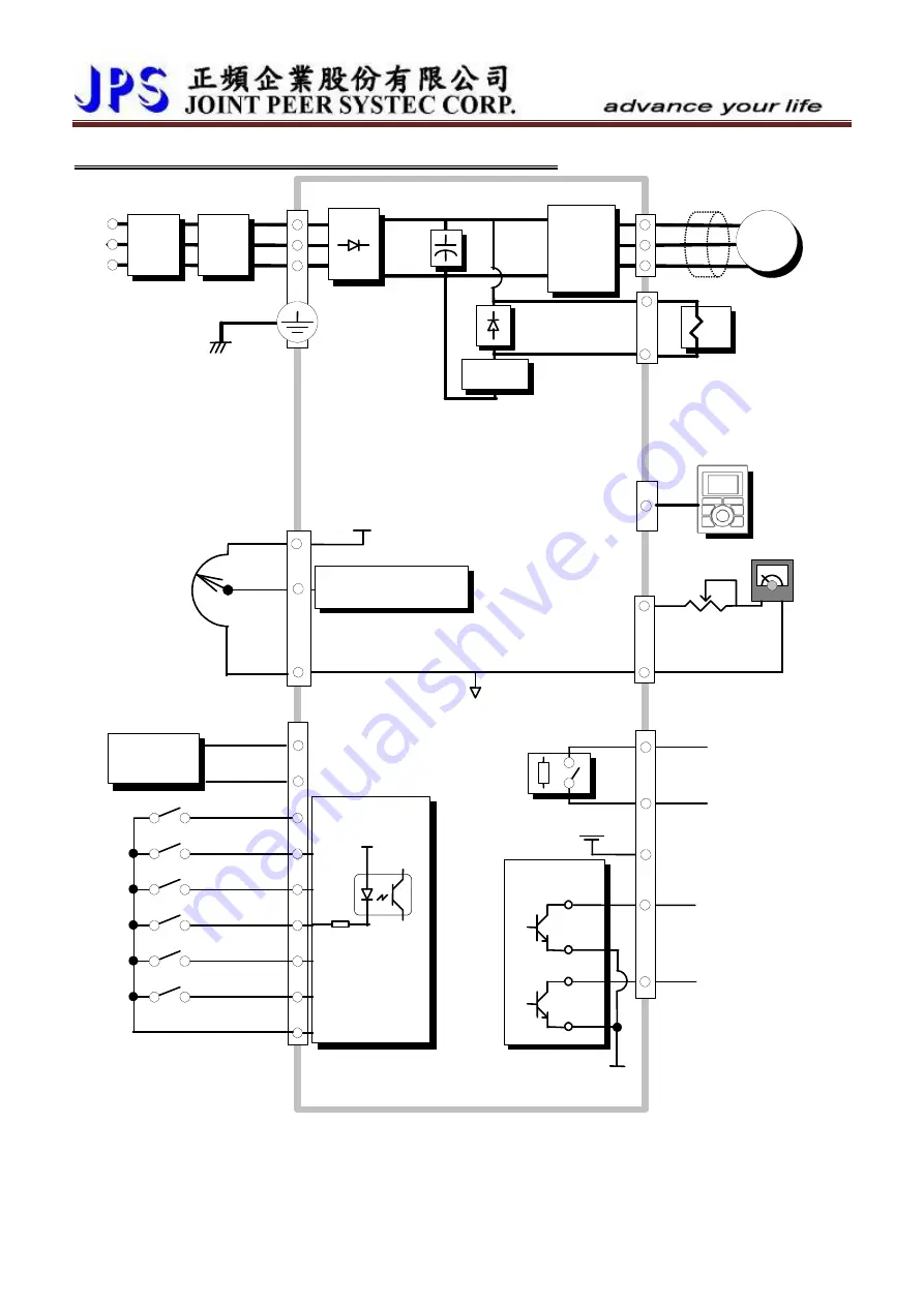
6.Basic Wiring Diagram for IRIS Series Drive
EMI
NFB
POWER
SOURCE
Filter
IGBT
0V ~ +10V RANGE
-10V ~ +10V RANGE
G24
REV
FWD
DI4
DI3
DI2
DI1
PHOTO
ISOLATED
DIGITAL
INPUT PORT
MOTOR
R
S
T
E
ACOM
V5T
ACOM
AM1
RY3A
RY3B
MAX. RATING
200V, 3A
OPEN
COLLECTER
24V
DO1
DO2
U
V
W
POTENTIAL
METER
AI1
BRAKE
24V
LCD-485
G24
DO3
24V
485-B
485-A
TO PLC
、
HMI
、、、
www.jps.com.tw
17
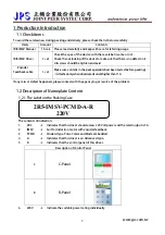
Содержание IRIS-IMSV
Страница 1: ...IRIS IMSV DRIVER USER MANUAL Version V5 03 ...
Страница 95: ...16 CE Certificate 16 1 EMC Certificate www jps com tw 94 ...
Страница 96: ...16 2 LVD Certificate www jps com tw 95 ...


