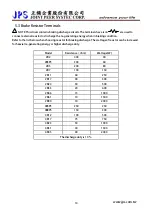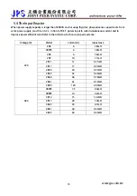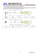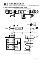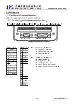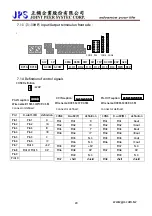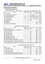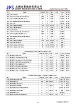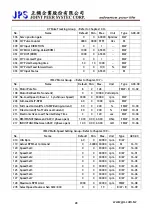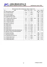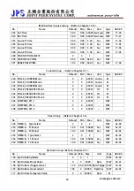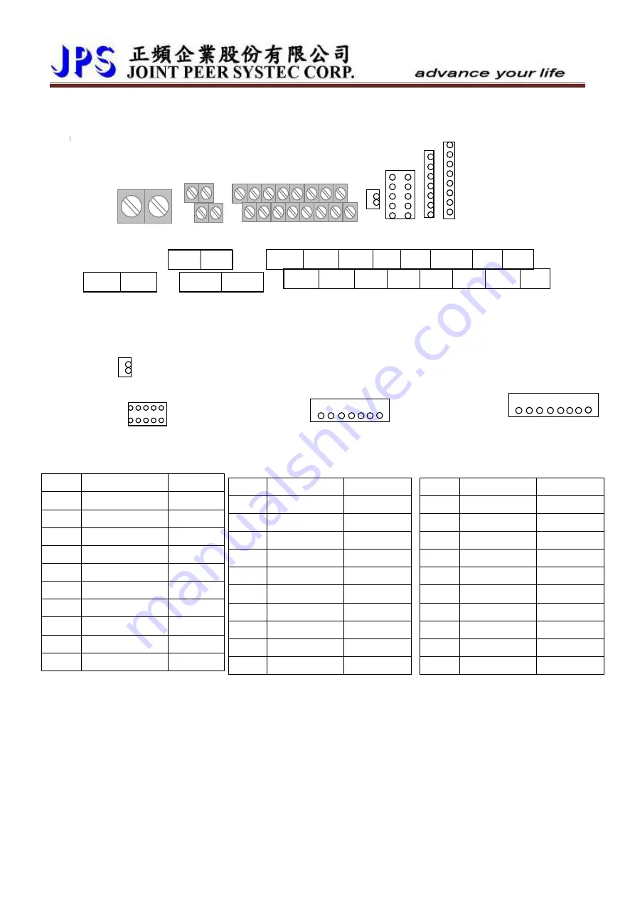
7.1.3【3~30HP】Input/Output terminal on front side:
A I 2
5 V
485A
485B
AM1
AI1
T5V
ACOM 24V G24
D O1
D O2
D I 1
D I 2
D I 3
D I 4 FWD REV
CON9 PG1 CON8 CON6
RY3A RY3B
ACOM ACOM
7.1.4
Definition of control signals
CON9 Definition
Æ
24V
www.jps.com.tw
20
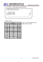
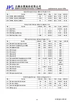
PG-IN caption:
Wire name:D15M-SJW10P-0.5M
XY-IN caption:
Wire name:D09F-SC07P-0.5M
Connector defined:
CON8
D-sub9(F)
definition
Pin1
Pin1
X
Pin2
Pin2
/X
Pin3
Pin3
Y
Pin4
Pin4
/Y
Pin5
N.C.
Pin6
N.C.
Pin5
Pin7
+5V
Pin6
Pin8
0V
Pin9
N.C.
Pin7
shell
shield
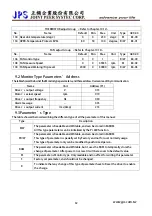
PG-OUT caption:
Wire name:D09M-SC08P-0.5M
Connector defined
:
CON6
D-sub9(M)
definition
Pin1
Pin1
Aout
Pin2
Pin2
/Aout
Pin3
Pin3
Bout
Pin4
Pin4
/Bout
Pin5
Pin5
Cout
Pin6
Pin6
/Cout
Pin7
N.C.
Pin7
Pin8
0V
Pin9
N.C.
Pin8
shell
shield
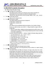
Connector defined:
PG1
D-sub15(M)
definition
Pin1
Pin1
A
Pin2
Pin2
/A
Pin3
Pin3
B
Pin4
Pin4
/B
Pin5
Pin5
C
Pin6
Pin6
/C
Pin7
Pin13
+5V
Pin8
Pin14/ Pin15
0V
Pin9
Pin10
Содержание IRIS-IMSV
Страница 1: ...IRIS IMSV DRIVER USER MANUAL Version V5 03 ...
Страница 95: ...16 CE Certificate 16 1 EMC Certificate www jps com tw 94 ...
Страница 96: ...16 2 LVD Certificate www jps com tw 95 ...

