5.Description of Wiring
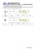
The upper cover must be removed in order to connect the electrical leads.
5.1Power Terminal
The power terminals are divided into three portions:
1.
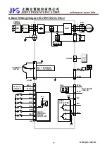
The power input terminals (R, S, T) receives power for the operation of the inverter.
2.
The output terminals (U, V, and W) deliver output power to motor.
3.
Brake resistor should be connects to icon
.
!
NOTE: The terminal has icon
should be connected to Earth properly.
!
WARNING: Never connect power source line to U, V, W, P, N, B terminals.
5.1.1The Power Input Terminals (R, S, T)
!
WARNING! NOTE!
z
The power input terminals are R, S, and T. Never connect power source line to U, V, W, P, N, B terminals.
z
Between the power source and driver, add NFB for system protection.
z
There are static sensitive components inside the Printed Circuit Board. Avoid touching the boards or
components with your hands or metal objects.
z
Make sure to connect the power terminals tight and correctly.
z
Make sure that the power source supplies the correct voltage and is designed for the necessary current.
z
The terminal has icon
should be connected to Earth properly.
5.1.2The Output Terminals (U, V, W to Motor)
z
Make sure the motor’s rated voltage and current are suitable with driver’s specification.
!
WARNING: Do not insert contactors between driver and motor; the U, V, W terminals should be connected
to motor directly.
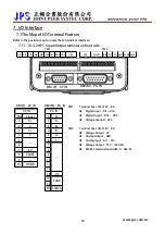
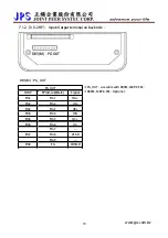
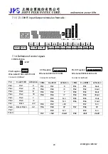
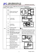
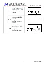
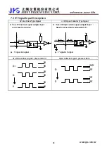
5.2The Control Signal Terminals
!
WARNING! NOTE!
All the input/output control signal lines, or remote panel lines and communication lines must be laid
separately from the high current power/motor/brake lines. They must not be fed through the same cable
conduit/trucking.
www.jps.com.tw
13
Содержание IRIS-IMSV
Страница 1: ...IRIS IMSV DRIVER USER MANUAL Version V5 03 ...
Страница 95: ...16 CE Certificate 16 1 EMC Certificate www jps com tw 94 ...
Страница 96: ...16 2 LVD Certificate www jps com tw 95 ...

